background image

9

Òàáëèöà/Table 5

Íàèìåíîâàíèå êîìïëåêòóþùåãî / Component denomination

Êîëè÷åñòâî, øò. (ýêç.) / Quantity, pcs (copies)

Áëîê/Unit

1

Ïàñïîðò/Passport

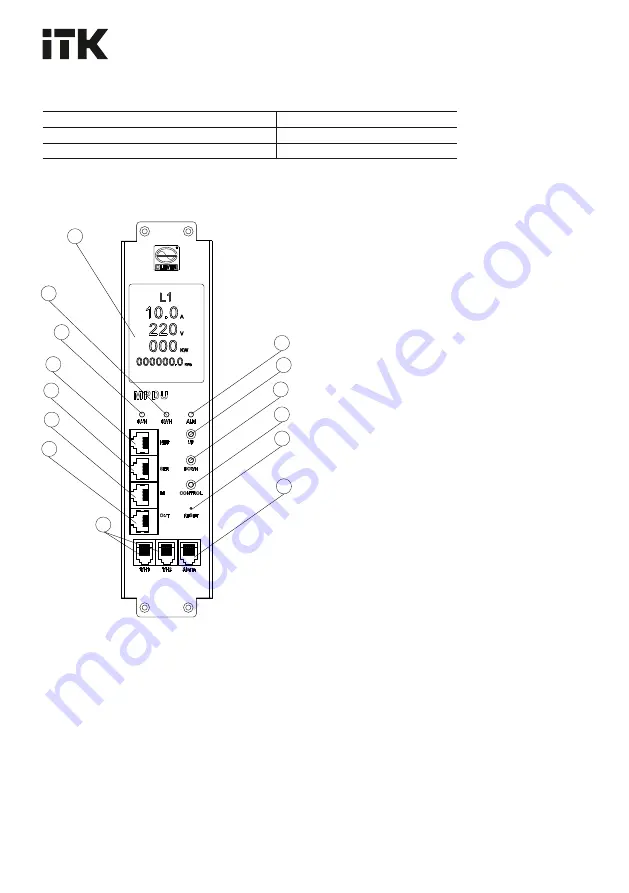
Ðèñóíîê 

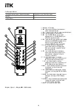
/ Figure 1 – 

Ìîäóëü NMC

 / NMC module

current consumption indicator;

5. NET 


ïîðò

 10/100M Ethernet 

ñî


âñòðîåííîé


6. SER – ñåðèéíûé ïîðò äëÿ ïîäêëþ÷åíèÿ èíòåðôåéñà 

3. RUN 


èíäèêàòîð


ðàáîòû


ìîäóëÿ

 / module operation indicator;

èíäèêàöèè


ðàáîòû

 / 10/100M Ethernet port 

ïîäêëþ÷åíèå ê âõîäó IN ñëåäóþùåãî PDU / 

2. kWh – èíäèêàòîð ïîòðåáëåíèÿ ýëåêòðîýíåðãèè / 

1. LCD-ýêðàí / LCD-display; 

4. ALM 


èíäèêàòîð


òðåâîãè

 / alarm indicator;

with built-in operation indication;

ñâÿçè (ïðîòîêîë MODBUS ïîääåðæèâàåòñÿ) / 

connection (MODBUS protocol is supported);

7. IN – ïîðò ïîñëåäîâàòåëüíîãî ïîäêëþ÷åíèÿ, 

ïîäêëþ÷åíèå ê âûõîäó OUT ïðåäûäóùåãî 

PDU / serial connection, connection to output 
OUT of foregoing PDU;

serial port for communication interface 

8. OUT – ïîðò ïîñëåäîâàòåëüíîãî ïîäêëþ÷åíèÿ, 

serial connection, connection to intput IN 

ñëåäóþùåãî

 of next PDU;

9. T / H1– ïîðò ïîäêëþ÷åíèÿ 1-ãî äàò÷èêà 

òåìïåðàòóðû


è


âëàæíîñòè

 / connection port of 

13. CONTROL – êíîïêà ïîäòâåðæäåíèÿ è ïåðåêëþ÷åíèÿ 

over the LCD-display page button;

button;

ñèãíàëèçàöèè

 / audio and visual alarm 

LCD-

ýêðàíà

 / previous page of the LCD-display 

the 1st temperature and humidity sensor;

1

4

. RESET – 

êíîïêà


ñáðîñà

 / reset button

10. Alarm – ïîðò ïîäêëþ÷åíèÿ çâóêîâîé è âèçóàëüíîé 

button;

12. DOWN – êíîïêà ïåðåõîäà ê ñëåäóþùåé ñòðàíèöå 

the 2nd temperature and humidity sensor;

ñòðàíèöû

 LCD-

ýêðàíà

 / confirm and switch 

connection port;

    T / H2 – ïîðò ïîäêëþ÷åíèÿ 2-ãî äàò÷èêà 

11. UP – êíîïêà ïåðåõîäà íà ïðåäûäóùóþ ñòðàíèöó 

òåìïåðàòóðû


è


âëàæíîñòè

 / connection port of 

LCD-

ýêðàíà

 / next page of the LCD-display 

1

2

3

5

6

7

8

4

11

12

13

14

10

9

Summary of Contents for ADMIN AN-PM13-24-18C13-06C19-41

Page 1: ...CONTROL ITK 004 2011 020 2011 037 2016 13 IEC 60320 1 AN PM13 24 18C13 06C19 41 AN PM13 24 21C13 03C19 41 N PM23 24 18C13 06C19 41 N PM23 24 21C13 03C19 41 NMC NMC 1 2 6 5 1 4 1 4 1 ADMIN PDU C CONTRO...

Page 2: ...bus IP 7 230 400 CONTROL 4 9 RUN NMC 11 20 70 10 20 70 95 25 2 NET PDU Ethernet CONTROL 8 WEB SNMP Telnet SMTP SMTPS MODBUS NTP www itk group ru 10 Google Chrome 50 Mozila Firefox 65 0 1 MS IE 11 Appl...

Page 3: ...of ADMIN series with monitoring general monitoring and control of CONTROL series of ITK trademark hereinafter unit is designed for power distribution in server racks data processing centers etc This...

Page 4: ...ical profile of the cabinet or rack bracket Connect the unit to 230 VAC or 400 VAC network by power cord with a plug to a suitable mains socket Unwind the power cord completely before connecting it Pr...

Page 5: ...of flexible cable mm minimum 3 6 5 6 Colour RAL 9005 black 12 1 019 Electric shock protection class I Overload protection circuit breakers 2 16 6 16 14254 IEC 60529 Degree of protection according to...

Page 6: ...Degree of protection according to IEC 60529 IP20 Operating temperature 0 45 From 0 to plus 45 Measurement parameters for displaying information on the unit display ower kW Voltage V PF Power factor PF...

Page 7: ...14254 IEC 60529 Degree of protection according to IEC 60529 IP20 Operating temperature 0 45 From 0 to plus 45 Measurement parameters for displaying information on the unit display urrent ower kW Volt...

Page 8: ...of protection according to IEC 60529 IP20 Operating temperature 0 45 From 0 to plus 45 Measurement parameters for displaying information on the unit display PF Power factor PF urrent Voltage V ower k...

Page 9: ...rial connection connection to output OUT of foregoing PDU serial port for communication interface 8 OUT serial connection connection to intput IN of next PDU 9 T H1 1 connection port of 13 CONTROL ove...

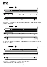
Page 10: ...1825 0 CN PM43 24 18C13 06C19 41 Figure 2 AN PM13 24 18C13 06C19 41 CN PM23 24 18C13 06C19 41 AN PM33 24 18C13 06C19 41 Figure 3 AN PM13 24 21C13 03C19 41 CN PM23 24 21C13 03C19 41 AN PM33 24 21C13 03...

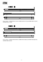
Page 11: ...3 AN PM33 36 24C13 12C19 43 CN PM43 36 24C13 12C19 43 CN PM43 42 36C13 06C19 43 Figure 6 AN PM13 42 36C13 06C19 43 CN PM23 42 36C13 06C19 43 AN PM33 42 36C13 06C19 43 1829 0 1825 0 1556 0 136 5 136 5...

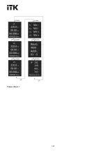
Page 12: ...12 Figure 7...

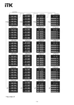
Page 13: ...13 Figure 8...

Page 14: ...14 Figure 9 Figure 10...

Page 15: ...15 Figure 11 Version 2...

Reviews: