IU_MAP_MANUAL_01i01_ENG
9 /20
3.2.
Application examples
3.2.1.
Circuit-breaker bay
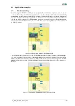
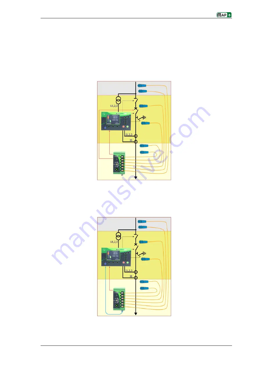
Connection diagram of MAP 6 in switchgear bay equipped with circuit-breaker. 6 optical sensors are used, 2
in each bay: busbar bay, circuit-breaker bay and terminals bay. One of relay output can be connected directly
to the breaker. Optional, second output can be connected to control bay device, for redundant protection
and proper information about tripping by the bay control device. For example this configuration can be used
in feeder bay, where opening of the circuit breaker cuts off an arc current. One of the optical inputs can be
also used to connect the MAP 6 device placed in another bay, where opening of the circuit breaker does not
cut off an arc current.
Fig. 3.2.1.1 Connection of MAP 6 in circuit-breaker bay
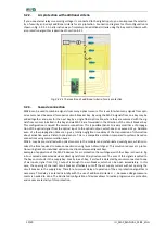
If you connect device as shown in Fig.3.2.1.2, you can adapt additional criteria of interlock for arc protection.
In that case you should not connect MAP 6 device with bay control unit directly. Instead of this optical output
of MAP 6 should be connected with optical input of bay control device and arc protection algorithm should be
activated with additional criteria. This solution allows use much more optical sensors than using only of con-
trol device.
Fig. 3.2.1.2 The insertion of additional criteria for arc protection


