background image

ITS Partner O.B.S S.L · Av. Cerdanyola 79-81 Local C 

08172 Sant Cugat del Vallés · Barcelona (Spain)  

Phone: +34935839543  ·  info@ek.plus  ·   www.ek.plus


4


CM COMPACT 8S4 

USER MANUAL


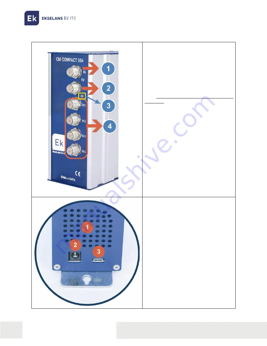
CONNECTIONS AND INTERFACES: 


1.- RF mix input connector. 


2.-  RF  output  connector.  This  output  will 
supply the MUX's generated by the module 
itself, plus those entering through connector 
number 1. 


3.-  Status  LED.  Displays  the  status  of  the 
input and output sequentially. This sequence 
starts  with  short  blinks  indicating  the 
coupling 

status 

of 

the 

selected 

demodulators.  Red:  not  coupled;  Green: 
coupled.  Followed  by  a  longer  blink 
indicating whether the modulator has started 
up or not. Red: not started up; Green: started 
up. 


4.- Input connectors to each tuner. 


1.- Ventilation grille. 


2.- Power supply connector. 


3.-  Micro-USB  B  communication  port  for 
connection to the PC. 

Summary of Contents for 085001

Page 1: ...79 81 Local C 08172 Sant Cugat del Vall s Barcelona Spain Phone 34935839543 info ek plus www ek plus USER MANUAL CM COMPACT 8S4 085001 4 input 8 tuner DVB S S2 multistream to COFDM QAM 4 RF adjacent...

Page 2: ...3 Package contents 3 CONNECTIONS AND INTERFACES 4 INSTALLATION AND CONNECTION 5 General installation and connection 5 CM Management PROGRAMMING SOFTWARE 6 Main screen 6 CM COMPACT 8S4 module configura...

Page 3: ...of each of the four inputs of the module 13 18V 22KHz DiSEqC A B C D Subsequently each tuner will be associated to the desired input Flexible remultiplexing of services on any output channel NIT table...

Page 4: ...f plus those entering through connector number 1 3 Status LED Displays the status of the input and output sequentially This sequence starts with short blinks indicating the coupling status of the sele...

Page 5: ...llite signals to the inputs of the CM COMPACT 8S4 unit 3 Important note Pay particular attention to the input type Follow the instructions on the front panel 4 Connect the power supply unit supplied R...

Page 6: ...or Windows operating systems version XP 7 and higher Once downloaded from the website www ek plus Software CM Headend section run the program after connecting the PC to the USB port This will ensure t...

Page 7: ...left corner By double clicking the button will change the colour to orange and the icon will change from grey to blue Clicking the icon will update the FW of the module It is recommended to update eac...

Page 8: ...ion Status View the unit status 3 Eight configuration options for the various satellite inputs separated by letters from A to H 4 Frequency configuration of the tuners from A to H 5 Frequency configur...

Page 9: ...dded Example If 11496Mhz is entered once the last number is pressed 1746 will automatically appear Calculation 11496 9750 1746 Symbol Rate Symbol Rate of the selected MUX Gold code Depending on the MU...

Page 10: ...ars indicating whether the service is TV or Radio and whether it is encrypted or open CI This module does not have a CI card OUTPUT MODULATION each circle corresponds to a MUX output 1 2 3 4 5 6 7 or...

Page 11: ...modify the identifier Freq MHz Center frequency of the first desired output channel E g CH21 474000 The first one is selected and the next three are adjacent CH22 CH23 CH24 B W Bandwidth of the outpu...

Page 12: ...d In this way all TV sets with the LCN function available will have the same content in each program number on the TV set Whilst this function is useful for hotels or cable operators as it avoids manu...

Page 13: ...proved For installations where there are problems with the MER Modulation Error Rate an improved performance of the product can be obtained in the event that it has been attenuated at the headend leav...

Page 14: ...USER MANUAL CONFIGURATION EXAMPLE 1 IN1 Hispasat Satellite Input A Frequency 11496MHz BIS 1746Mhz 11496 9750 Polarity Horizontal LOW SR 7884 Code Root 185747 Stream 0 2 IN2 Astra Satellite Input B Fr...

Reviews: