PS200 Configuration & Operation Guide
OPTIONS & FEATURES
Page 83
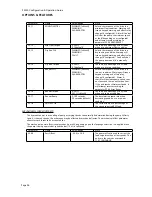
Motor Thermal Protection
The motor can be protected against overheating by the motor thermal protection function. The default method of
protection is a motor temperature thermal model created by the PS200. The PS200 calculates the temperature of
the motor assuming an ambient temperature of 30 C (86 F) when power is applied to the PS200. The thermal
model can be User adjusted if the ambient temperature exceeds 30 C (86 F). Refer to your PumpSmart
Applications group for guidance.
NOTE - Parameters 24.05 and 24.06 are in the Advanced Parameter Group accessible by User Pass Code 564.
Parameter
Name
Value/Range
Notes
24.05
MOTOR THERM PROT
WARNING
[default]
FAULT
NO
This parameter defines the reaction of
PumpSmart when it calculates a
potential motor thermal fault. FAULT
will shut the pump down. NO will result
in no warning or fault shutdown.
24.06
MOTOR THERM PMODE
DTC
[default]
USER MODE
THERMISTOR
This defines how PumpSmart will
determine a motor thermal fault. DTC
uses the ABB DTC control algorithm
while THERMISTOR uses a physical
thermistor placed in the motor.
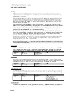
An alternate method of detecting motor overheating is by use of a motor thermistor. The thermistor or a break
contact of a thermistor relay is connected between the PS200 in24 VDC voltage supply and digital input 4
(DI4). Under normal motor temperature operation the thermistor resistance should be less than 1.5kohm (current
5 mA). The PS200 will warn the user or fault (see parameter 24.05) if the thermistor resistance exceeds 4 kOhm. If
using a motor thermistor, parameter 25.06 Secondary Protect A must be set to “Thermistor”.
NOTE - Parameter 24.06 Motor Thermal P Mode will automatically update to the Thermistor setting.
Parameter
Name
Value/Range
Notes
25.06
SECONDARY PRTCT A
DISABLED
[default]
ALARM & CTRL
THERMISTOR
Select THERMISTOR when a motor
thermistor is wired at DI4
!
!! WARNING !!
According to IEC664, the connection of the motor thermistor to a digital input requires double or
reinforced insulation between motor live parts and the thermistor. Reinforced insulation entails a
clearance and creeping distance of 8 mm (0.31 in) for 400/500 VAC input voltages. If the thermistor
assembly does not fulfill the requirement, the other I/O terminals of the drive must be protected
against contact, or a thermistor relay must be used to isolate the thermistor from the digital input.
1 DI1
2 DI2
3 DI3
4 DI4
5 DI5
6 DI6
7 +24 VDC
8 +24 VDC
9 GROUND
10 GROUND
11 DIIL
X22
DIGITAL SWITCH POWER SOURCE
DIGITAL SWITCH POWER SOURCE
DIGITAL SWITCH GROUND
SETPOINT SELECTION
SECONDARY PRTCT B
DIGITAL RESET
SECONDARY PRTCT A / THERMISTOR
DIGITAL SWITCH GROUND
DRIVE PERMISSIVE
OPT
OPT
START/STOP
2 WIRE/HOA Configuration
MANUAL OVERRIDE
2 WIRE/HOA Configuration
OPT
OPT
OPT
OPT
OPT
OPT
OPT
OPT
OPT
Motor
T
10 nF
1 DI1
2 DI2
3 DI3
4 DI4
5 DI5
6 DI6
7 +24 VDC
8 +24 VDC
9 GROUND
10 GROUND
11 DIIL
X22
DIGITAL SWITCH POWER SOURCE
DIGITAL SWITCH POWER SOURCE
DIGITAL SWITCH GROUND
SETPOINT SELECTION
SECONDARY PRTCT B
DIGITAL RESET
SECONDARY PRTCT A / THERMISTOR
DIGITAL SWITCH GROUND
DRIVE PERMISSIVE
OP
T
OP
T
START/STOP
2 WIRE/HOA Configuration
MANUAL OVERRIDE
2 WIRE/HOA Configuration
OP
T
OP
T
OP
T
OP
T
OPT
OP
T
OPT
OP
T
OPT
Motor
T
Thermistor
Relay
OP
TI
O
N
1
OPTIO
N
2
Summary of Contents for PumpSmart PS200
Page 1: ... PUMPSMART CONTROL SOLUTIONS PS200 Version 4 0 Configuration Operation Guide ...
Page 2: ......
Page 4: ......
Page 8: ......
Page 26: ......
Page 72: ......
Page 105: ......
Page 119: ......
Page 146: ...PS200 Configuration Operation Guide APPENDIX A 3 PARAMETER LISTING Page 143 ...
Page 147: ......
Page 158: ......


