PS200 Configuration & Operation Guide
OPTIONS & FEATURES
Page 85
Regulation Mode
The regulation mode can either be NORMAL or INVERSE. The common selection is NORMAL, where the drive
anticipates an increase in the process condition when pump speed is increased. If the regulation mode is set to
INVERSE, the process condition is expected to increase with a decrease in pump speed.
EXAMPLE – If a PumpSmart unit is trying to control the level in a suction-side tank or sump, the regulation mode
would be set to INVERSE. As the level in the sump increased, PumpSmart would respond by increasing pump
speed to maintain a constant level.
Parameter
Name
Value/Range
Notes
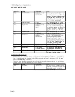
21.01
REGULATION MODE
NORMAL
[default]
INVERSE
Inverse is normally used for control of
suction side systems.
Relay Outputs
The PS200 has three relay outputs that are configurable for different operating and fault conditions. Relays will
revert to original states once warnings or faults are reset or cleared.
Relay Output Technical Information
Switching capacity
8A at 24 VDC or 250 VAC
0.4 at 120 VDC
Maximum continuous current
2 A RMS
Refer to the ACS800 Hardware Manual for complete technical details.
Parameter
Name
Value/Range
NOTES
NOT USED
RUNNING
READY
Default for RO3
Default for RO2
Default for RO1
VFD FAULT
A VFD related warning or fault has
occurred
PUMP FAULTS
A general pump warning or fault has
occurred
ALL FAULTS
Both Pump and VFD warnings and faults
LOW PMP PERF
Pump Performance has degraded
SECND PRTECT A
Secondary Protect A activation
SECND PRTECT B
Secondary Protect B activation
HIGH VIBRAT
High vibration alarm/fault
PUMP PROTECT
Pump protection activation
START SLAVE
Used with multi-pump macro only
HI CONDITION 1
Condition 1 protection activation
HI CONDITION 2
Condition 2 protection activation
19.01
19.04
19.07
RELAY R01 OUTPUT
RELAY R02 OUTPUT
RELAY R03 OUTPUT
PROC TX ERR
Process transmitter protection activation
NOTE – When using relay outputs to activate constant speed pumps in a multi-pump application, the slave pumps
1, 2, and 3 must utilize relay outputs RO1, RO2, and RO3 accordingly (Slave 1
Æ
RO1). Sequence logic is affected
by these selections.
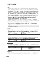
Restart Options
See MINIMUM SPEED OPTIONS
Summary of Contents for PumpSmart PS200
Page 1: ... PUMPSMART CONTROL SOLUTIONS PS200 Version 4 0 Configuration Operation Guide ...
Page 2: ......
Page 4: ......
Page 8: ......
Page 26: ......
Page 72: ......
Page 105: ......
Page 119: ......
Page 146: ...PS200 Configuration Operation Guide APPENDIX A 3 PARAMETER LISTING Page 143 ...
Page 147: ......
Page 158: ......


