background image

Enclosure 6N  Temperature Switches     

Page 3


WARNING 

WARNING 

WARNING 

WARNING 

CHAPTER


INSTALLATION AND 

OPERATION


Installation of these Neo-Dyn

®

 Enclosure 6N temperature 

switches is straightforward. However, they must be installed by a 
qualified electrician, in compliance with all local and national 
electrical codes. 

Electrical Hazard 

Do not make electrical connections while power is on. 

Always check for multiple circuits. 

Always make sure grounding is adequate. 

MOUNTING 

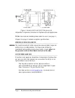
Model 100T can be mounted directly to the process connection if 
there is no significant vibration and the fluid lines are capable of 
supporting the weight. It can also be attached to a flat surface, 
such as a wall or panel, using .250 in. diameter or M6 socket-head 
cap screws through the mounting holes that are accessed by 
removing the housing cover; allow .5 in (12.7 mm) screw length 
above the mounting surface. These holes are located on two 
corners of a 2.72 inch (6.91 cm) square, or 3.85 inches (9.77 cm) 
apart on a 45° diagonal. Model 100TC must be mounted by this 
method, as its remote temperature sensor will not support the 
housing. Do not overtighten the screws when replacing the cover. 

Summary of Contents for 100T

Page 1: ...NEO DYN MODELS 100T AND 100TC ADJUSTABLE TEMPERATURE SWITCHES ENCLOSURE 6N FOR EXPLOSIVE ATMOSPHERES INSTALLATION AND OPERATION MANUAL PN 610 0014 E ...

Page 2: ......

Page 3: ...al injury death or substantial property damage if the warning is ignored Indicates a hazard which will or can cause minor personal injury or property damage if the caution is ignored Indicates additional information about a particular item necessary to the operation of the unit The Electrical Snap Switch Assemblies shall be installed such that the equipment wiring is protected from mechanical dama...

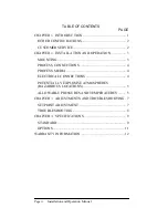
Page 4: ...LLATION AND OPERATION 3 MOUNTING 3 PROCESS CONNECTIONS 4 PROCESS MEDIA 4 ELECTRICAL CONNECTIONS 4 POTENTIALLY EXPLOSIVE ATMOSPHERES HAZARDOUS LOCATIONS 5 ALLOWABLE PRESSURES AND TEMPERATURES 5 CHAPTER 3 ADJUSTMENTS AND TROUBLESHOOTING 7 SETPOINT ADJUSTMENT 7 TROUBLESHOOTING 8 CHAPTER 4 SPECIFICATIONS 9 STANDARD 9 OPTIONS 11 WARRANTY INFORMATION 12 ...

Page 5: ...rature sensor Model 100T has a Teflon seal while Model 100TC has a graphite filled non asbestos packing Setpoint adjustments are easily made through the adjustable range by turning an adjustment nut located inside the housing The standard configuration of these switches will switch up to 11 amp at 125 or 250 VAC 5 amp resistive at 28 VDC or 0 5 amp resistive at 125 VDC When ordered with M Option t...

Page 6: ... except adhere to the pressure and electrical limits marked on the units CUSTOMER SERVICE If you have any questions about these Temperature Switches that are not covered in this manual you can contact Neo Dyn or our representatives in several ways The Neo Dyn customer service phone number is 661 295 4000 Our customer service department is open from 7 00 am to 3 30 p m Pacific Time Our Internet sit...

Page 7: ...00T can be mounted directly to the process connection if there is no significant vibration and the fluid lines are capable of supporting the weight It can also be attached to a flat surface such as a wall or panel using 250 in diameter or M6 socket head cap screws through the mounting holes that are accessed by removing the housing cover allow 5 in 12 7 mm screw length above the mounting surface T...

Page 8: ...ipe joint sealing compound Avoid excessive torque on all threaded connections PROCESS MEDIA Process media must be compatible with the wetted materials listed in Chapter 4 starting on page 10 Compatibility is defined by an A rating in the Chemical Resistance Guide for Metals and Alloys and as applicable the Chemical Resistance Guide for Plastics or the Chemical Resistance Guide for Elastomers All a...

Page 9: ...dous locations in accordance with the National Electric Code NEC and applicable UL and CSA specifications ALLOWABLE PRESSURES AND TEMPERATURES Do not exceed the 1500 psig 103 5 bar Maximum Operating Pressure System Pressure in normal operation The 2250 psig 155 1 bar Proof Pressure is provided to give the maximum allowable pressure without causing permanent damage to the temperature switch in the ...

Page 10: ...Page 6 Installation and Operation Manual Similarly the marked Proof Temperature is the maximum temperature the process media could reach in an over temperature condition without damaging the switch ...

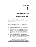
Page 11: ...e rotated by hand or with an open end wrench or similar tool The range scale indicates the increasing setpoint and is intended to be used only as an approximate guide Make precise final adjustments using the measurements described in para 4 and 5 below 4 To check the increasing setpoint of a temperature switch insert the temperature probe into a fluid bath so that the hex is within 3 8 inch 9 5 mm...

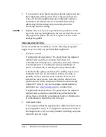
Page 12: ...contamination in the process connection and verify that the expected pressure is reaching the sensing diaphragm or piston or temperature is reaching the temperature probe If the Belleville spring can be heard to audibly snap but an ohmmeter indicates no electrical switching the cause is probably stuck or burned switch contacts or the switch element has moved away from the position where it was syn...

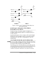
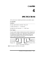
Page 13: ...ber The part number contains information about which configurations and options are included in your Adjustable Temperature Switch To determine the sensing range electrical rating and options compare the part number of your unit with the information in Figure 3 below and the following tables 100T 3 B CC 6 MN Model Series Options Wetted Material Explosion Proof Elec Range Letter Elec Form C or CC F...

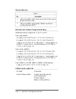
Page 14: ...AC to 60 C 140 F max T6 5 amp 125 or 250 VAC 5 amp resistive 3 amp inductive 28 VDC 5 amp resistive 04 amp inductive 125 VDC to 70 C 158 F max T6 Form CC6N DPDT 11 amp 125 or 250 VAC to 65 C 176 F max T4A 11 amp 125 or 250 VAC to 45 C 116 F max T6 5 amp 125 or 250 VAC 5 amp resistive 3 amp inductive 28 VDC 5 amp resistive 04 amp inductive 125 VDC to 70 C 158 F max T6 Form C6MN or CC6MN SPDT or DPD...

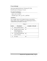
Page 15: ...pe 3 3R 3S 4 4X 13 NEMA OPTIONS The available options for standard switches are listed below These options can be combined every included option will be indicated in the part number of the unit Table 2 Option Description Available on Model A Epoxy painted exterior All M Gold Electrical Contacts For Extremely Low Current Applications All W Corrosion resistant steel screws exterior All X CE mark All...

Page 16: ...lusion from Warranty THE FOREGOING WARRANTY IS IN LIEU OF AND EXCLUDES ALL OTHER EXPRESSED OR IMPLIED WARRANTIES OF MERCHANTABILITY OR FITNESS OR OTHERWISE Components manufactured by any supplier other than ITT shall bear only the warranty made by the manufacturer of that product and ITT assumes no responsibility for the performance or reliability of the unit as a whole In no event shall ITT be li...

Reviews: