www.ittcontrols.com
contact@ittcontrols.com
12
Section 3
Model 581A Differential Pressure Switch
Tools
The following tools are recommended for general maintenance of the Model
581A differential pressure switch.
Table 3.1—Tools
Equipment
Purpose
Pointer Puller
Pointer removal
Small Screwdriver
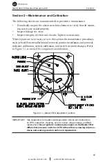
Calibration adjustment
Medium Screwdriver
Bezel removal and replacement
1/4" and 1/8" Open-end Wrenches
Zero (1/4") and Range (1/8") adjustments
1/8 Hex Allen Wrench
Switch set point adjustment
Bezel/Lens Assembly or Cover Installation and Removal
To remove the bezel/lens assembly or cover, loosen the screws on the front
and lift the assembly or cover from the enclosure.
To reinstall the bezel/lens assembly (581A-0 only), install the O-ring in the
groove of the case, assemble the bezel, lens, and lens gasket, and realign the
screw holes with the holes in the case. Then, reinstall the screws in the bezel
to secure all components to the case. Torque the screws per
Table 4.3, page 30
.
To reinstall the cover (581A-2), install the O-ring in the groove of the case
and realign the screw holes in the cover with the holes in the case. Reinstall
the screws in the cover to secure it to the case. Torque the screws per
Table
4.3, page 30
.
IMPORTANT: Ensure the bezel gasket is properly oriented before placing the instru-
ment back in service. Incorrect gasket orientation will cause the instru-
ment indicator to jam, resulting in inaccurate readings.
Calibration Check
To ensure the unit calibration is within factory-set calibration tolerances,
perform the following procedure.
IMPORTANT: Review all procedures and WARNINGS/NOTICES in Appendix A
BEFORE performing this procedure.
1. Mount the instrument in an approximately level position and connect to a
standard pressure source.
2. If the zero indication is incorrect, adjust it as follows:
a. Remove the bezel/lens assembly or cover.
b. Using a 1/4" open-end wrench (included in calibration toolkit, Part


