background image

www.ittcontrols.com

contact@ittcontrols.com

8

Section 1  

Model 581A Differential Pressure Switch

Summary of Contents for BARTON 581A

Page 1: ...zel Lens Assembly or Cover Installation and Removal 12 Pointer Installation and Removal 13 Pointer Installation 13 Pointer Removal 14 Scale Plate Installation and Removal 14 Indicator Calibration 15 Drive Arm Tightness Test 17 Drive Arm Stop Adjustment 17 Switch Calibration 17 Calibration Setup 18 Linkage Calibration Procedure 18 Changing Switch Set Point 20 20 Best Practices for Set Points 20 Cha...

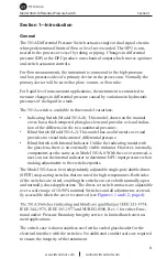
Page 2: ...l indication of differential pressure Blind Switch with Internal Indicator Unlike the indicating model with the glass lens there is no externally visible indicator However internally components are the same as in Model 581A 0 With the cover removed a user can use the internal indicator to determine DPU input pressure when making adjustments to the switch setpoints The Model 581A uses two independe...

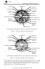
Page 3: ...th indicator internal components Left Switch Right Switch Left Switch Lock Screw Plunger Screw Actuating Cam Left Switch Adjustment Assembly Switch Adjust Linkage Plunger Screw Right Switch Lock Screw Terminal Strip Switch Adjust Linkage Right Switch Adjustment Assembly Cam Actuator Switch Adjustment Assembly includes crank index shaft and index pointer Figure 1 2 581A without indicator internal c...

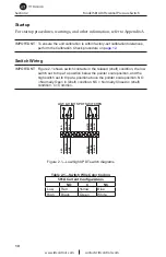
Page 4: ...YELLOW RED YELLOW BLUE SWITCH CLOSED CONTACTS OPEN CONTACTS GREEN WHITE GREEN BLACK A LEFT B RIGHT YELLOW BLUE YELLOW RED SWITCH A LEFT SWITCH B RIGHT SWITCH A LEFT SWITCH B RIGHT Notes 1 CAM ROTATES COUNTER CLOCKWISE WITH INCREASED DIFFERENTIAL PRESSURE 2 EACH SWITCH MAY BE SET AT ANY POINT FROM 10 TO 90 OF DP RANGE 3 WIRES No 22 AWG Internal and No 18 AWG External Figure 1 3 Switch wiring connec...

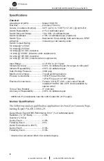
Page 5: ...ression Input Range 0 10 WC to 0 115 psid Indicator Accuracy 2 0 of calibrated span for ranges to 400 psid 1 Indicator Repeatability 0 5 of calibrated span Safe Working Pressure 3000 psig Maximum Overrange To safe working pressure Process Connections 1 4 NPT top and bottom 1 2 NPT top and 1 4 NPT bottom Electrical Connections Female 3 4 NPT 20 ft color coded Tefzel insulated 18 AWG wire 40 ft lead...

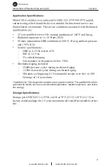
Page 6: ...ent pressure and 95 R H OBE 6 25 Gs series of 5 SSE 12 5 Gs 5 critical damping No resonance in frequencies below 33 Hz Mechanical aging included 25 000 pressure cycles during accelerated aging 12 500 electrical cycles during accelerated aging Vibration cycling using 0 2 G sinusoidal sweeps over the 1 to 200 Hz range at 1 0 octave min 1 governed by factors such as environmental temperature radiatio...

Page 7: ...www ittcontrols com contact ittcontrols com 8 Section 1 Model 581A Differential Pressure Switch ...

Page 8: ...nse spectra at mounting surface of the instrument shall not exceed those conduit shall be supported by the same mounting as the DP instrument base in order to minimize relative motion of the DP instrument and connections Dimensional drawings are provided in Section 5 page 32 See Appendix A for Model 199 DPU installation and maintenance informa tion Electrical Connection Units are supplied with dua...

Page 9: ...ows switch contacts in the relaxed shelf condition the low switch set to trip at a position below the pointer scale position and the high switch set to trip at a position above the pointer scale position NO Normally Open in shelf condition NC Normally Closed in shelf condition C Common LOW HIGH SPDT SWITCHES NO NO C C NC NC RED YELLOW BLUE RED YELLOW BLUE WHITE GREEN BLACK WHITE GREEN BLACK 1 2 3 ...

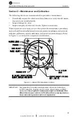
Page 10: ...ry When repairs are necesssary review this section for maintenance procedures such as bezel lens installation and removal pointer installation and removal indicator calibration switch calibration and switch set point changes Refer Figure 3 1 Model 581A adjustment controls IMPORTANT See Appendix A for related warning caution notices and instructions on DPU inspection cleaning service repair range c...

Page 11: ...einstall the screws in the bezel to secure all components to the case Torque the screws per Table 4 3 page 30 To reinstall the cover 581A 2 install the O ring in the groove of the case and realign the screw holes in the cover with the holes in the case Reinstall the screws in the cover to secure it to the case Torque the screws per Table 4 3 page 30 IMPORTANT Ensure the bezel gasket is properly or...

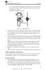
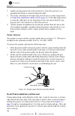
Page 12: ...oximately 5 to 10 above the full scale mark 5 Apply 0 50 and 100 of full scale pressure If the indication is within Scale Plate Installation and Removal page 14 6 Make sure the instrument zero indication is correct otherwise repeat step 2 7 Verify the switch set points refer to Changing Switch Set Point page 20 Pointer Installation and Removal During adjustment and calibration of the unit it may b...

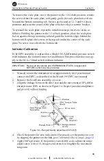
Page 13: ... the following steps 1 Slide the pointer puller along the pointer until the pin protruding from the tip of the screw in the pointer puller is directly over the movement shaft and the arms of the pointer puller are directly under the pointer 2 Gently turn the knurled head of the screw clockwise pushing the pin against the movement shaft and lifting the pointer with the arms Finger required an Allen...

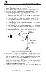
Page 14: ...on If the DPU assembly is replaced on a Model 581A differential pressure switch with indicator the indicator must be recalibrated This procedure does not ap ply to the 581A 2 blind switch without indicator IMPORTANT Review all procedures and WARNINGS NOTICES in Appendix A BEFORE performing this procedure 1 Securely mount the instrument in an approximately level position and connect the DPU as desc...

Page 15: ...rew until it is snug to the shaft d Still supporting the block shaft tighten the clamp screw an addition al 1 3 to 1 2 turn This screw can normally turn one full revolution before breaking e Perform the Drive Arm Tightness Test described on page 17 1 8 WRENCH PN 9A 0163 0044C CLAMP SCREW DRIVE ARM LINK SINTERED CLAMP BLOCK TO TIGHTEN 03 approx M199 SHAFT Figure 3 5 Drive arm to torque tube connect...

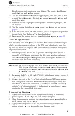
Page 16: ...er at normal 0 torque tube rotation position 0 on a normal 0 to 100 scale unit adjust the drive arm stop bracket or use alternate means to prevent the pointer from moving the stop bracket interferes with drive arm movement IMPORTANT On reverse acting split range units it will be necessary to pressurize the DPU to move the pointer to the minimum scale position On suppressed units it will be necessa...

Page 17: ...ot All switch mounting screws are tight Linkages are straight and do not bind at the pivots Correct any problems that are observed If no problems are observed proceed with a complete calibration SWITCH ACTUATOR ARM STOP SCREW PLUNGER SCREW CAM ROLLER CAM Figure 3 6 Switch mechanism Calibration Setup 1 Connect an output device lamp or buzzer to the switch output leads 2 Connect a test voltage to th...

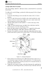
Page 18: ...ter to index number 1 on the outer edge of the switch index 4 Apply 10 differential pressure and adjust the switch plate until the switch actuates Lock the two linkage screws 5 Rotate the index pointer to index number 9 Apply 90 differential pressure and adjust the crank radius until the switch actuates 6 Recheck 10 and 90 set points Adjust the crank radius and the index pointer until both set poi...

Page 19: ...ex Allen wrench Set Point The measured pressure at which the snap switch actuates and thereby changes the states of the N O and N C contacts For example the set point of the low switch is 24 psid with decreasing pressure Deadband The difference in measured pressures between switch actuation and switch reset Deadband is usually expressed as percentage of full scale of F S Deadband is not adjustable...

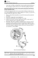
Page 20: ... cover Do not remove the pointer or scale plate 2 Insert hex wrench in the switch adjust post 3 Loosen the switch lock screw item B 1 2 to 1 turn 4 With the hex wrench move the index pointer item C to the new set point as indicated on the switch index item D 5 If possible check the set point by varying the process pressures and ob serving the pointer readings when the switch actuates Open the mani...

Page 21: ... Change the switch set point as described in Changing Set Point of an In Service Instruments page 21 5 Check the set point by changing measured pressure to actuate the switch For example To verify a low switch set point of 24 psid apply approxi mately 30 psi Reduce pressure to approximately 25 psid hold for a few seconds then continue in 1 4 psid steps until the switch actuates If the set point is...

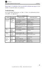
Page 22: ... movement Tighten or replace Out of calibration Calibrate Pointer loose Tighten pointer Dirty or corroded mechanism Clean or replace Wiring interfering with move ment Re route wiring Dirty mechanism Clean mechanism High Indication Indicator Alarm Switch Mechanism Loose linkage or movement Tighten or replace Out of calibration Calibrate Erratic Indication Indica tor Alarm Switch Mechanism Linkage d...

Page 23: ...uator in the switch Examine circuits for voltage amperes DC inductive loads cause arcing and burning of contacts Consider arc suppression devices or relays Vent gas or drain liquids from signal lines Calibration Techniques Failure to check set point after locking Verify set point repeatability after locking switch plate Rapid pressure change or vent ing system During calibration make pressure chan...

Page 24: ...25 Model 581A Differential Pressure Switch Section 4 Section 4 Assembly Drawing and Parts List LOCATE THE SCALE PLATE UNDER THE MOUNTING TAB WITHOUT A SCREW AT THE 6 O CLOCK POSITION Figure 4 1 Model 581A 0 indicating switch shown with glass lens ...

Page 25: ...9A C0257 0019C 2 9 Lock Screw 9A C0580 1017C 2 10 Screw B H Slotted 3 48 x 3 16 Lg 9A C0117 0007J 6 11 Washer Flat No 3 9A C0003 0045K 11 12 Screw B H Slotted 8 32 x 3 16 Lg 9A C0117 1001J 2 13 Retaining Ring 9A C0087 0015T 2 14 Grip Ring 9A C0087 0011T 2 15 Link Plate 9A C0288 0016C 2 16 Set Screw 6 32 x 1 4 Lg 9A C0320 1010J 1 17 Strap 9A C0288 0017C 2 18 Washer Flat 9A C0317 0019C 2 19 Set Scre...

Page 26: ... 47 O ring Torque Tube EPT 9A C0001 1069R 1 48 Ring Grip 9A C0087 1029T 1 49 Washer Split Lock 3 8 9A C0003 0093K 2 50 O ring Header EPT 9A C0001 1066R 1 51 Nut Hex 3 8 16 9A C0500 0039J 2 52 O ring Lens Cover EPT 9A C0001 1057R 1 53 O ring Plug EPT 9A C0001 1051R 1 54 Set Screw Socket Hex 10 32 x 3 8 Lg 9A C0320 0024J 2 55 Screw Rd Hd Slotted 6 32 x 3 16 Lg 9A C0117 0013J 2 56 Scaleplate select o...

Page 27: ...www ittcontrols com contact ittcontrols com 28 Section 4 Model 581A Differential Pressure Switch Figure 4 2 Model 581A 2 blind switch without indicator ...

Page 28: ... B H Slotted 8 32 x 3 16 Lg 9A C0117 1001J 2 13 Retaining Ring 9A C0087 0015T 2 14 Grip Ring 9A C0087 0011T 2 15 Link Plate 9A C0288 0016C 2 16 Set Screw 6 32 x 1 4 Lg 9A C0320 1010J 1 17 Strap 9A C0288 0017C 2 18 Washer Flat 9A C0317 0019C 2 19 Set Screw Hex Socket 6 32 x 3 8 Lg 9A C0320 1015J 2 22 Drive Arm Assembly 9A C0581 1008B 1 24 Block Terminal TB1 9A CS054 0011Z 1 28 Bracket Terminal Bloc...

Page 29: ...Item 38 cap screw before installing Apply Locktite to Item 19 set screw when installing into the mounting plate Table 4 3 presents torque requirements for the switch assembly fasteners Table 4 3 Torque Requirements for Switch Assembly Fasteners See Figures 4 1 and 4 2 for part Item Description Part No Per Unit Torque 9 Lock Screw 9A C0580 1017C 2 Tight 10 Screw B H Slotted 3 48 x 3 16 Lg 9A C0117 ...

Page 30: ...g Model 581A 0 only 9A C0117 0013J 2 Tight 44 Screw Hex Head 3 8 16 x 3 4 Lg 9A C0116 0007J 4 25 30 ft lb 46 Plug 9A C0224 0269C 1 Snug 51 Nut Hex 3 8 16 9A C0500 0039J 2 22 25 ft lb 55 Screw Rd Hd Slotted 6 32 x 3 16 Lg 9A C0117 0013J 2 Tight 58 Screw Socket Flat Hd 3 8 16 x 1 Lg 9A C0240 00004J 1 22 25 ft lb 59 Screw Hex Hd 3 8 16 x 1 Lg 9A C0116 0006J 1 25 30 ft lb Snug denotes 1 16 approx turn...

Page 31: ...www ittcontrols com contact ittcontrols com 32 Section 4 Model 581A Differential Pressure Switch ...

Reviews: