background image


IMPORTANT 

It must be taken into account that an exit must be left for the air that the machines 

takes  through  the  front  louver.  It  can  be  a  back  hole  (with  an  outdoor  exit)  or  a 

louver on the machine. 

The  water  connection,  drainage  and  electrical  steps  of  the  equipment  are  also 

necessary. (see the figure) 


Anchoring of the machine 

Follow the following steps: 

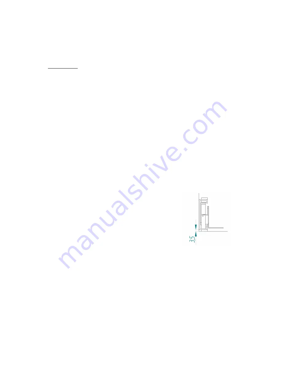
1-  Screw  the  guides  in  the  hole  of  the  piece  of  furniture  to  have  them 

horizontally and set back 5 mm as it is indicated on the figure. 


Summary of Contents for HNG

Page 1: ...TECHNICAL INSTALLER S MANUAL ICE CUBE MANUFACTURER HNG MODEL ...

Page 2: ...his machine should not be used by children or handicapped without the proper supervision and monitoring Children should be monitored to assure that they do not play near the equipment This machine is not intended to be used outdoors nor exposed to the rain Connect the equipment to the drinking water network The machine should be connected using the power cable supplied with the equipment The conne...

Page 3: ... of the next ice cycle and the excess goes to the drainage through the maximum level overflow tank Once the specified time goes by the hot gas and water entry valves close The pump starts and sends water through the injectors against the molds of the cubes where the ice is formed little by little At the same time the evaporation temperature decreases until the cubes are completely made When this p...

Page 4: ...SPECIFICATIONS MAIN DIMENSIONS Profundidad Hueco Opening Depth Altura hueco Opening Height ...

Page 5: ...er 15 C Production Kg 24 h 10 Cycle period of time minutes 38 Ice cubes per cycle 12 Weight per ice cube gr 22 1 Obtained data with Envt 20ºC water intake T 15ºC and water quality 500ppm 2 Obtained maximum consumption at Envt 43ºC according to UNE rules for the T Class climatic classification TROPICALIZED NOTE Controlled expansion per capillary RECEPTION OF THE MACHINE Inspect the outside packing ...

Page 6: ...LLATION Location zone conditions The HNG machines are designed to operate at room temperature between 5ºC 41ºF and 43ºC 109 40ºF There may be some difficulties in ice cube removal under the minimum temperatures Above the maximum temperature the life of the compressor is shortened and the production is substantially less The machines take air for the ventilation on the front part and they expel the...

Page 7: ...fect in the piece of furniture has the dimensions established in the drawing 560x440x560 mm The drainage must be in the position established in the drawing In the left part of the housing and below the inferior level of the machine In this way the flexible pipes have the enough path to allow the extraction of the machine Hueco ventilación Ventilation opening Hueco salida desagüe Drainage output op...

Page 8: ...Toma agua Water connection Toma Eléctrica Power Inlet Salida desagüe Drainage Output Zona libre para paso de la máquina Free space for machine clearance ...

Page 9: ......

Page 10: ...ck hole with an outdoor exit or a louver on the machine The water connection drainage and electrical steps of the equipment are also necessary see the figure Anchoring of the machine Follow the following steps 1 Screw the guides in the hole of the piece of furniture to have them horizontally and set back 5 mm as it is indicated on the figure ...

Page 11: ... machine in the position of the drawing 3 Screw the fastening flanges of the drainage hoses 4 Place the machine on the support angles of the guides Adjust the wide before fastening the screws checking that it slides softly along the path ...

Page 12: ...recommend the installation of a filter of 5 micron b WATER WITH MORE THAN 1000 PPM The ice will be less hard and will stick a bit in the stock There can be ice cubes with white marks In the machine there will be lime deposits that can interfere with its good operation Water hardness is corrected with the installation of a good decalcifier c VERY CHLORATED WATER The ice gives a bleach chlorine tast...

Page 13: ...e enough path to allow the extraction of the machine it is convenient that the drainage pipe has an entry with an interior diameter of 50 mm to introduce the two drainage hoses of the machine Fix the pipes with the flanges that were provided Thus we ensure that when taking out and storing the machine the pipes do not come out Electrical connection The machine is provided with a 1 5 m 4 92 feet cab...

Page 14: ...arges connected and operating d Are the air circulation and site temperature appropriate ROOM CONSUMPTION MAXIMUM 43ºC 109 40ºF 35ºC 95ºF MINIMUM 5ºC 41ºF 5ºC 41ºF e Is water pressure appropriate MINIMUM 1 kg cm2 MAXIMUM 5 kg cm2 NOTE If the inlet pressure of the water is superior to 5 kg cm2 install a pressure reducer START UP Once the installation instructions are followed ventilation site condi...

Page 15: ... injectors send water to the evaporator on the right direction during the manufacturing process even spread 9 After 10 minutes verify that the water container has no leakages through the maximum level retainer 10 Verify that after the final cycle the frost on the aspiration pipe is at 50 mm 0 78 in of the compressor 11 Check that during the fall of the ices there is no water lose 12 Introduce the ...

Page 16: ...free of damages Maintenance and cleaning intervals will depend on the conditions of the location and water quality CAUTION INSTRUCT THE USER ABOUT MAINTENANCE PROCEDURES INDICATING THAT THIS ONE AS WELL AS DAMAGES DUE TO LACK THEREOF ARE NOT COVERED BY THE WARRANTY CAUTION At least one revision and cleaning should be performed every six months On dusty environments it might be necessary to clean t...

Page 17: ... the container Exterior Cleaning 0000 Depending on the local conditions Depending on the water conditions and quality TO BE DONE BY THE USER ESSENTIAL MAINTENANCE AND CLEANING OPERATION AS WELL AS DAMAGES DUE TO THE LACK OF SUCH OPERATIONS ARE NOT INCLUDED ON THE WARRANTY The technical installer shall invoice traveling costs hours and materials used on such operations MAINTENANCE AND CLEANING PROC...

Page 18: ...til the water container is empty Place the overflow 4 Close the water inlet 5 Refill the system until the maximum level of the water container with the same solution Connect the machine the water must be closed and wait 20 minutes 6 Open the water connect the machine CAUTION Eliminate the ice manufactured in this first cycle NOW THE SANITARY CLEANING STARTS 6 Connect the machine and once there is ...

Page 19: ...n Exterior Cleaning Use the same procedure as the one indicated for the ice storage bin Collectors and Injectors 1 Remove the shield Take the time to clean it with phosphoric acid clean with bleach and clear under water 2 Remove the louver of ice drop Clean as done with the shield 3 PULL THE COLLECTOR UPWARDS IT IS PRESSURE MOUNTED 4 Disassemble the injectors and lids and clean them 5 Disassemble ...

Page 20: ...nd clean it under water Water Leak Control When working on the machine always check the water connections status of the clamps and hoses with the purpose of avoiding leakages and prevent damages or floods Electronic operation This machine operates by means of the digital electronic controller adapted for ice cubes in ITV GALA DELTA manufactures In the front part of the machine we can see the displ...

Page 21: ... amount of cycles before the machine stops 4 Ice cube size By default the size is 5 increase or decrease the size with the arrows press OK in the desired size 5 Language By default the language is Spanish choose the language with the arrows OK in the desired language To exist press menu The used values are maintained memorized in the following starts up with out electrical shutdowns Technical inst...

Page 22: ... and other outlets Modify Arrows up down OK 6 Removal time The removal time will indicate the seconds that we want the removal to last The controller will recalculate this time in function of the temperature of the environment and the water Modify Arrows up down OK 7 By default This option will return all the parameters of the machine to the standard default configuration By pressing both arrows y...

Page 23: ...the set point temperature is reached until the removal begins Complete T gives us the sum of manufacturing time plus removal time 3 Cooling T Removal T Cooling T shows us the time that passes until the set point temperature is reached from the end of the removal Removal T during the removal and cooling gives us the time used during the last removal During the manufacturing process it will show a b...

Page 24: ...Inputs Storage bin thermostat 1 Security Pressure Switch 2 Flooding 3 Free Input 4 Outputs Compressor Fan 1 Pump 2 Electrovalves 3 Free Output 4 I 1234 O 1234 ...

Page 25: ...ine air inlet Remove the objects that block the air flow Dirty ventilation filter clean with water Dirty condenser Clean the condenser Short time Machine is stopped Ice cake formation in the machine Check condensation and water inlet pressure The showers do not water The pump does not work Change the pump The impulse tube is loose Press the tube by its joints Long time Machine is stopped The compr...

Page 26: ...nections and connection cable E Stop thermostat badly regulated or faulty E Check and regulate or change 6 All the electric organs are working The compressor doesn t work A Loose cable A Check connections B Faulty compressor relay B Change the relay C Faulty Klixon C Change the Klixon D Faulty compressor D Change the compressor 10 All the electric organs are working the Klixon compressor A Low vol...

Page 27: ... B Change C No water enters the container C Check water inlet electrovalve and change if necessary D The water container is left without water D Check the overflow pipe and possible water losses E There s humidity in the system F Change the dehydrator generate vacuum and load F Inefficient refrigeration system dirty condenser damaged or badly regulated pressure switch or condensation water inlet v...

Page 28: ...ulate reducing manufacturing time 34 I Faulty or wrongly connected hot gas valve I Check and eventually change 35 Low ice production A Dirty condenser air flow blocked or hot air is received from another device A Clean condenser release air flow or change the machine location 37 C Hot gas valve is faulty it always lets some hot gas the tube temperature indicates so C Replace the hot gas valve 38 D...

Page 29: ...perly they are blocked and loose water C Adjust the shield slats or clean the shaft it may have calcareous incrustations that prevent the smooth rotation of the slats 48 The machine doesn t stop not even when it s full of ice cubes A Stock thermostat badly regulated or faulty A Regulate and or change 49 The cubes are melted in the stock container A Blockage in the machine or installation drainage ...

Reviews: