Chapter 10
Appendix
ITW Dynatec
UFD Applicator, Manual 40-43, Rev. 6.16
Page 105
Chapter 10
Appendix
Solenoid Valve Configurations, Schematics & Setup
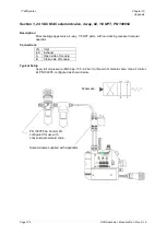
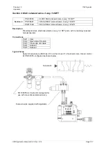
This Appendix covers the pneumatic setup of the solenoid valves used to actuate the adhesive
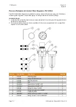
modules. A coalescing filter/ regulator kit (PN 100055) is available to provide regulated, oil-free air to
the solenoid valves. The kit also contains the necessary fittings and tubing to configure the kit for each
particular solenoid valve.
Some typical solenoid valve setups are shown on the following pages. While the most commonly used
solenoid valves are shown, other valves not listed here may be used if required for the particular
application. In general, however, the setups shown here can be applied to any solenoid valve. If there
are questions about a valve that was supplied with the Applicator, and it is not shown here, consult
ITW Dynatec.
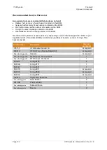
The Appendix is divided into sections for easy reference:
Section 1
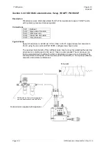
PN 100054
24 VDC MAC solenoid valve, 4 way, 02, 1/8 NPT
Section 2
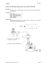
PN 100383
24 VDC MAC solenoid valve, 4 way, 1/4 NPT
PN 100421
120 VAC MAC solenoid valve, 4 way, 1/4 NPT
PN 811506
240 VAC MAC solenoid valve, 4 way, 1/4 NPT
Section 3
PN 106937
24 VDC MAC solenoid valve, 5 way, 1/8 NPT
Section 4
PN 112496
24 VDC MAC solenoid valve, 4 way, 1/4 NPT
Section 5
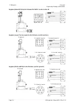
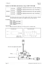
PN 113350
24 VDC Festo high speed solenoid valve, 4 way, 6mm inlet fitting,
2.5m cable
PN 113451
24 VDC Festo high speed solenoid valve, 4 way, 1/4 inlet fitting,
2.5m cable
PN 114558
24 VDC Festo high speed solenoid valve, 4 way, 6mm inlet fitting,
10m cable
PN 114559
24 VDC Festo high speed solenoid valve, 4 way, 1/4 inlet fitting,
10m cable
Section 6
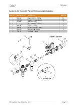
PN 100055
Component Illustration: 100055 Air Control Kit
Air Filter/ Regulator Installation Notes
1. Compressed air for Applicator operation should be clean, dry and oil free.
2. In general, operation of more than one Applicator from a single air control kit is not recommended,
because Applicator response time may be increased and synchronization may be more difficult.
3. Install the filter/ regulator so that the bowl drains are easily accessible for servicing and the
regulator knob is accessible for adjustments.
4. Use a minimum of 1/4” OD tubing to make connections.
5. If air tubing is routed close to the Applicator due to space constraints, high temperature TFE tubing
should be used to avoid tubing damage.

