


Chapter 4
Installation & Startup
ITW Dynatec
UFD Applicator, Manual 40-43, Rev. 6.16
Page 27
2. Connect the compressed-air supply to Applicator. Connect all solenoids with air hoses
as required.
6 bar air pressure are required.
Reason:
•
Lower air pressure causes uneven adhesive application.
•
The modules do not switch or switch with delay, resp. open and close again, if the air
supply is uneven.
•
Only permanent pressure and sufficient volume flow leads to reproducible application
accuracy regarding position and amount.
CAUTION: Do not use lubricating oil with the air supply as Applicators are
lubricated at the factory and do not require lubrication when used in production.
Where oil is present in the air supply, a coalescing filter (Dynatec PN 100055) must
be installed between the standard air regulator/ filter and the UFD Applicator.
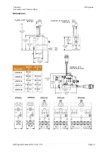
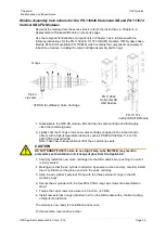
UFD Applicators require at least one solenoid valve for each applicator. If your head was
ordered without a solenoid valve, a 4-way valve (or a 5-way valve for snuffback modules)
should be mounted so that the air lines to each Applicator are as close to the same length
as practical.
Note: Air lines and fittings must be capable of withstanding temperatures up to 218°C
(425°F). ITW Dynatec supplies Air Control Filter Coalescing Kits (PN 100055) to be used
with air-operated Applicators (see the Air Control Filter Coalescing Kit Manual in
Appendix A of this manual).
For process (preheater) air control, the filter/ regulator kit PN 107404 is recommended. It
contains a 0-50 psi air filter/ regulator combination and a liquid-filled gauge for accurate
process air control.
See the Process (Preheater) Air Control Filter/ Regulator information in Appendix B.
When connecting the air lines to the applicator, the air line which has air pressure to the
module when the solenoid is OFF is the closing air line. See Appendix A and B for details
and diagrams of solenoid setup.
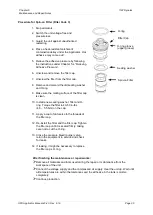
3. If a pre- or post- filter pressure transducer is to be utilized: install the supplied adapter
into the desired accessory port. Thread the transducer into the adapter (transducer
adapter has 1/2-20 thread). Follow the transducer manufacturer’s recommendations
for torque specifications. Note: the alternate hose inlets on either side of the Applicator
can also be used for the transducer adapter.
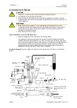
4. Before making the adhesive connection to the Applicator, align the adhesive supply
hose with its electrical connector oriented in relation to the electrical connector on the
top of the Applicator.
Connect the swivel fitting of the hot melt hose to the adapter on the service block,
using either the inlet port located below the filter nut or the port located on the top of
the Applicator (beside the electrical connection in the diagram). When tightening the
hose fitting, hold the hose cuff to prevent the hose core from rotating.
Heed the following for the installation of the heated hoses:
•
Heated hoses may be damaged by overheating, if they are laid faulty.
•
The heated hoses may not be stacked one on the other!
•
The heated hoses may not be pressed together and / or bound.
•
Put the hoses separated next to each other!
•
The connections for supply resp. return hoses may not be mixed up.
•
It is essential that the hoses will be laid without twisting!
•
Heated hoses may not be fastened with binders or similar.
•
Heated hoses may not be laid on a sharp edge.
•
When using a balancer, a hose support with a radius of 400mm has to be mounted.
Reason:
The sensor cables and heating cables within the hoses can be damaged. As
they cannot be repaired the hose would have to be changed completely.


