ITW Dynatec
Chapter 5
Maintenance and Repair Notes
Page 48
UFD Applicator, Manual 40-43, Rev. 6.16
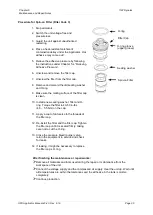
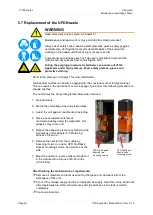
4. Remove the four screws holding the left-side cover plate. Remove the plate.
5. Pull the sensor out of the service block.
6. Cut the old sensor wires off as close to the sensor as possible.
7. Apply a thin film of thermal paste to the new sensor and place it in the service block.
Trim the lead wires so that they overlap the old sensor wires by one to two inches.
Strip the ends of all four wires.
8. Use the high-temp splice kit to connect the new sensor to the old sensor wires.
9. Place the wires in the wiring cavity and replace the left side cover.
The Applicator is now ready for installation and service.
Replacement of Air Preheater Temperature Sensor
WARNING
Heed all security advices given in Chapter 5.1.
Maintenance and repair work is only permitted for skilled personnel!
Note: a High-Temp Splice Kit (PN 102645) is required for this procedure.
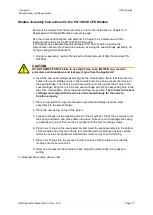
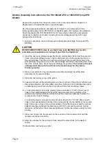
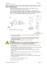
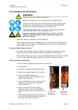
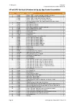
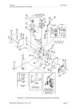
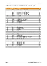
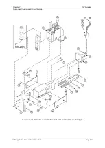
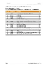
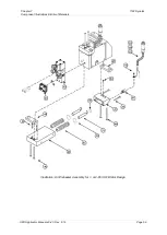
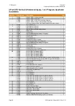
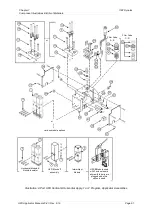
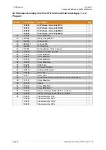
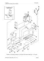
See illustration on pages for parts locations.
1. Stop all motors.
2. Turn the ASU OFF and relieve all system pressure.
Switch the unit voltage-free and pressureless.
Guard the unit against unauthorized restarting.
Relieve the adhesive pressure by following the instructions under Chapter 5.4
“Relieving Adhesive Pressure”.
3. Disconnect the service block’s electrical cable assembly from the hose and disconnect
the preheater’s cable assembly from its cable extension.
4. Remove the left-side cover plate.
5. Pull the sensor out of the preheater.
6. Cut the old sensor wires off as close to the sensor as possible.
7. Apply a thin film of thermal paste to the new sensor and place it in the service block.
Trim the lead wires so that they overlap the old sensor wires by one to two inches.
Strip the ends of all four wires.
8. Use the high-temp splice kit to connect the new sensor to the old sensor wires.
9. Replace the left side cover plate.
The Applicator is now ready for installation and service.


