background image

ITW Dynatec 

Chapter 7 

Component Illustrations & Bills of Materials 


Page 88


UFD Applicator, Manual 40-43, Rev. 6.16


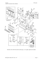
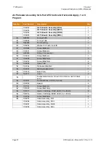
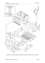
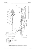
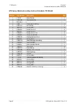
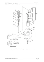
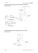
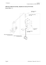
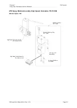
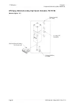
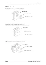
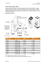
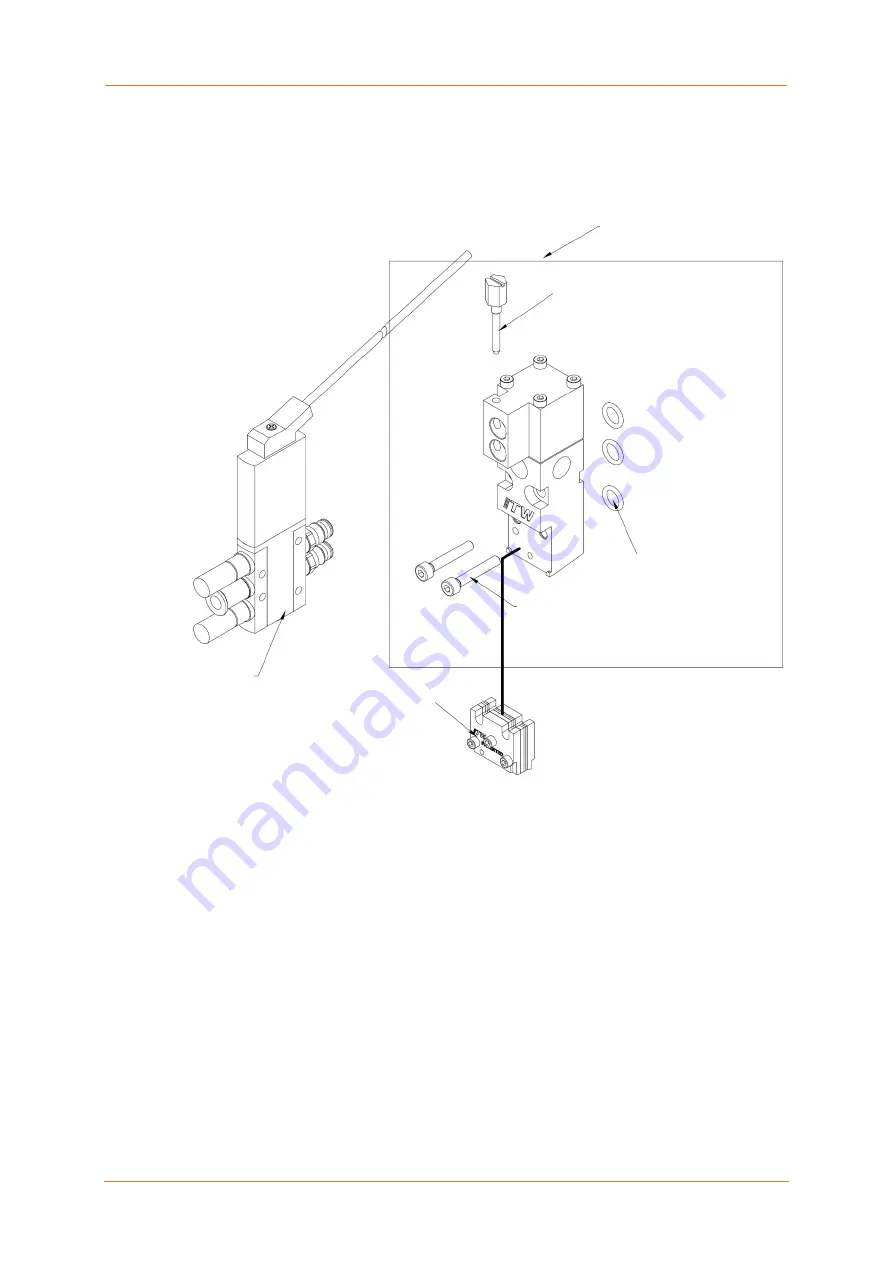
UPD Spray Module Assembly, High Speed, Vertical, PN 113346 

(Module Option “J”)


Module Assembly 
PN 113346 

Solenoid Retaining Ring 
PN 113348 

3x O-ring 2-011 
PN N00178 

2x Screw M4x25mm 
PN 100908 

High Speed Nozzle Assembly 

(for reference only) 

High Speed Solenoid Assembly 

(for reference only) 

Summary of Contents for DynaFiber UFD

Page 1: ...Adhesive Application Solutions ISO 9001 certified DynaFiber UFD Spray Applicator 1 6 Port Technical Documentation ITW Dynatec An Illinois Tool Works Company www itwdynatec com ...

Page 2: ...vice personnel read and understand this information Contact your ITW Dynatec customer service representative for additional copies NOTICE Please be sure to include the serial number of your application system each time you order replacement parts and or supplies This will enable us to send you the correct items that you need ITW Dynatec Service Parts Direct Dial 1 800 538 9540 ITW Dynatec Technica...

Page 3: ...on to environmental protection standards 16 Chapter 3 Description and Technical Specs 17 3 1 Applicable Safety Regulations 17 Intended Use 17 Unintended Use Examples 17 Residual Risks 17 Technical changes 18 Using foreign components 18 Setting up operation 18 3 2 Description of UFD Spray Applicator 19 Description 19 Technical Data 21 Model Designation Guide 22 Dimensions 23 Chapter 4 Installation ...

Page 4: ...r Preheater Assembly for 1 or 2 Port UFD Slim Design 58 2 Port UFD Vertical Horizontal Apply 1 or 2 Program Applicator Assemblies 60 Air Preheater Assembly for 2 Port UFD Vertical Horizontal Apply 1 or 2 Program 62 3 Port UFD Vertical Horizontal Apply 1 2 or 3 Program Applicator Assemblies 64 Air Preheater Assembly for 3 Port UFD Vertical Horizontal Apply 1 or 3 Program 66 Air Preheater Assembly f...

Page 5: ...acket Assembly PN 107622 98 Extension Cable Assemblies 99 Strand Coating System SCS 100 Recommended Service Parts List 102 Chapter 9 Engineering Drawings Schematics 103 Pin Connectors Electrical Schematics 103 Chapter 10 Appendix 105 Solenoid Valve Configurations Schematics Setup 105 Air Filter Regulator Installation Notes 105 Section 1 24 VDC MAC solenoid valve 4 way 02 1 8 NPT PN 100054 106 Sect...

Page 6: ...ITW Dynatec Index Page 6 UFD Applicator Manual 40 43 Rev 6 16 This page intentionally left blank ...

Page 7: ...Chapter 1 Declaration of Incorporation ITW Dynatec UFD Applicator Manual 40 43 Rev 6 16 Page 7 Chapter 1 Declaration of Incorporation ...

Page 8: ...ITW Dynatec Chapter 1 Declaration of Incorporation Page 8 UFD Applicator Manual 40 43 Rev 6 16 ...

Page 9: ...dous situations 4 Inspect the machine for unsafe conditions daily and replace all worn or defective parts 5 Keep work area uncluttered and well lit Remove all material or things not needed for the production from the workspace of the equipment 6 All covers and guards must be in place before operating this equipment 7 Subject to technical modifications without notice 8 To ensure proper operation of...

Page 10: ... spaced apart from each other not making direct contact 3 Do not use adhesive that is dirty or that may be chemically contaminated Doing so can cause system clogging and pump damage 4 When adhesive hand held applicators or other movable applicators are used never point them at yourself or at any other person Never leave a hand held applicator s trigger unlocked when not actually in use 5 Do not op...

Page 11: ... presence of moisture care must be taken to prevent them from curing inside ITW Dynatec equipment If PUR adhesive solidifies in a unit the unit must be replaced Always purge old PUR adhesive from the system per your adhesive manufacturer s instructions and time table ALLOWING PUR ADHESIVE TO CURE IN A UNIT OR ITS COMPONENTS VOIDS ITW DYNATEC S WARRANTY Eye Protection Protective Clothing WARNING EY...

Page 12: ... the defective components immediately Lockout Tagout Switch the unit voltage free before working Main switch OFF 1 Follow OSHA 1910 147 Lockout Tagout Regulation for equipment s lockout procedures and other important lockout tagout guidelines 2 Be familiar with all lockout sources on the equipment 3 Even after the equipment has been locked out there may be stored energy in the application system p...

Page 13: ...ir can remain within it causing hot adhesive and pressure to escape without warning when a filter cap or a hose or hydraulic connection is loosened or removed For this reason always wear eye protection and protective clothing 4 Either of the two High Pressure symbols shown may be used on ITW Dynatec equipment 5 Keep the given operating pressure 6 Notify the maintenance personnel immediately if hos...

Page 14: ...osened during the repair or maintenance if they are tight again 8 Replace the air hoses in preventive maintenance regularly even if they have got no viewable damages Adhere to the manufacturers instructions 9 Never clean control cabinets or other houses of electrical equipment with a jet of water 10 Adhere to the current safety data sheet of the manufacturer when using hazardous materials cleaning...

Page 15: ...and or an emergency medical technician immediately Let the burns medicate by a medic immediately Measures in case of fire 1 Please heed that not covered hot parts of the engine and molten hot melt may cause heavy burns Risk of burns 2 Work very carefully with molten hot melt Keep in mind that already jelled hot melt can be very hot too 3 When working near a hot melt application system always wear ...

Page 16: ...have to be fulfilled 2 Keep attention that during installations repairs or maintenance matters hazardous to water like adhesive adhesive scrap lubricating grease or oil hydraulic oil coolant and cleaner containing solvent not pollute the ground or get into the canalization 3 These matters have to be caught kept transported and disposed in appropriate reservoirs 4 Dispose these matters according to...

Page 17: ...ntially explosive atmosphere With unsuitable operating processing materials When the values stated under Specifications are not complied with The UFD Applicator may not be used to process the following materials Toxic explosive and easily flammable materials Erosive and corrosive materials Food products Residual Risks In the design of the UFD Applicator every measure was taken to protect personnel...

Page 18: ... foreign components ITW Dynatec takes no responsibility for consequential damages caused by using foreign components or controllers that have not been provided or installed by ITW Dynatec ITW Dynatec does not guarantee that foreign components or controllers used by the operating company are compatible to the ITW Dynatec system Setting up operation We recommend asking for an ITW Dynatec service tec...

Page 19: ...icator is determined by the adhesive pressure applied by the Adhesive Supply Unit s ASU s pump the nozzle type and the stem stroke adjustment As shown in the illustration below the heated adhesive supply hose may be connected at the rear of the applicator or at the top Adhesive flows from the hose into the service block through the filter and then to the module Air pressure Control Air opens the m...

Page 20: ... UFD Spray Applicator Filter Cap Glue Inlet Alternate Hose Inlet Process Air Inlet Air Preheater Fiberizing Nozzle Piston Accessory Port UFD Module Control Air Inlet Electrical Connection Alternate Glue Inlet Mounting screw Nozzle Filter Basket O ring Filter Nut Lock Nut Optional Drain Purge Valve Stroke Adjustment Screw ...

Page 21: ... including module and solenoid valve Model UFD0501 3 52 kg 7 75 lb Mounting M6 x 1 screws with insulators or 1 2 rod mount insulated clamps 12 to 13 mm rod Temperature range 38 C to 218 C 100 F to 425 F Warm up time 15 minutes for cold start 5 minutes for module change only Adhesive viscosity 100 to 30 000 mPa sec 100 to 30 000 centipoise Adhesive pressure range 68 bar maximum 1000 psi maximum Noi...

Page 22: ...SB manifold air H Horizontal UFD continuous V Vertical UFD continuous K Horizontal UFD SB intermittent F Vertical UFD SB intermittent J Vertical Hi Speed SB intermittent Festo M Horizontal Hi Speed SB intermittent Festo P Horizontal Hi Speed SB manifold air No of Modules installed 1 2 3 4 5 6 or Z no modules Voltage 2 240VAC Control D DynaControl PLC M MCV N Upgrade Nor Nickel RTD L Upgrade Mel J ...

Page 23: ...40 43 Rev 6 16 Page 23 Dimensions Dynafiber UFD Applicator side view Dynafiber UFD Applicator front view Dynafiber UFD SlimLine Applicator Width Centers Model No A B UFD0501 50mm 2 UFD0502 50mm 2 25 2mm 1 UFD0753 75mm 3 50 4mm 2 UFD1004 100mm 4 75 6mm 3 UFD1506 150mm 6 126mm 5 ...

Page 24: ...ITW Dynatec Chapter 3 Description and Technical Specs Page 24 UFD Applicator Manual 40 43 Rev 6 16 This page intentionally left blank ...

Page 25: ...wer and temperature control for the air preheater if applicable is supplied by a cable extension from the ASU Pneumatic connection In any case the air has to be clean and dry See advice in Chapter 4 3 Quality of compressed air Please heed that units with high air demand may not be used at the same time with the same air supply Incoming module activation air is supplied through a solenoid valve It ...

Page 26: ...hat permit lateral and vertical adjustments Mount the Applicator on a 12mm to 13mm rod or bracketry using the 6 mm screws and insulators provided Allow access to the filter Be sure that the stroke limit adjustment screws are accessible and that the weep holes are visible for periodic inspection Leave sufficient clearance to install a pressure transducer if applicable and allow access to a drain va...

Page 27: ...hen connecting the air lines to the applicator the air line which has air pressure to the module when the solenoid is OFF is the closing air line See Appendix A and B for details and diagrams of solenoid setup 3 If a pre or post filter pressure transducer is to be utilized install the supplied adapter into the desired accessory port Thread the transducer into the adapter transducer adapter has 1 2...

Page 28: ...cator of air and oil Turn the Applicator ON electrically and pneumatically WARNING HIGH PRESSURE HOT ADHESIVE During the purging procedure hot adhesive and oil can come out of the Applicator under high pressure Wear safety glasses gloves and protective clothing Use a stable deep container to collect hot melt adhesive and or oil Remove the nozzle from the module Place a heat resistant container und...

Page 29: ...uring Applicator installation the drain valve can be relocated to the left side of the Applicator for access if necessary The drain valve consists of a valve body with a rotatable outlet collar that directs the flow of adhesive A plug is located inside the body retained by a snap ring to prevent the plug from being fully removed Operation 1 Ensure that all pumps in the ASU Adhesive Supply Unit are...

Page 30: ...he adhesive pump to purge the hoses and Applicators of old adhesive Purge until the adhesive exiting the modules is fresh 3 Check system pressure to see if filters are clogged and need to be changed 4 Replace the nozzles and check the adhesive flow through them Compare to target flow 5 Check the nozzle spray pattern 6 Clean any nozzles that do not spray properly and check the spray pattern again 4...

Page 31: ... and adhesive pressure Risk of injury or heavy burns Always assume that the system is under pressure proceed with caution Keep a cool pack or bucket of clean water near the work area Place a heat resistant catchment container underlay under the components Hot adhesive may come out CAUTION At working temperature molten adhesive could cause heavy burns Let spilled out adhesive cool down first before...

Page 32: ... fittings until their shoulders are firmly seated Excessive torque may damage straight threaded parts and the use of power wrenches is not recommended HOT MELT RESIDUE must be cleaned from parts before they are re assembled particularly from threaded parts As a precaution against adhesive residue preventing proper re assembly threaded parts must always be re tightened at operating temperature 5 3 ...

Page 33: ...release the adhesive pressure in the Applicator before performing such maintenance 1 The Applicator should be at operating temperature 2 Turn the ASU s pump motor OFF 3 Place a heat resistant catchment container underlay under the Applicator Relieving Adhesive Pressure Manually 1 Push the purge button located on the side of the air solenoid coil Or if the ASU filter block is equipped with a drain ...

Page 34: ...apter 7 for more information The applicator must be at operating temperature Procedure for Basket type Filter Filter Codes A B 1 Stop all motors 2 Switch the unit voltage free and pressureless 3 Guard the unit against unauthorized restarting 4 Place a heat resistant catchment container underlay under the Applicator Hot adhesive may come out 5 Relieve the adhesive pressure by following the instruct...

Page 35: ... new sealing washer filter and O ring Torque the filter to 40 50 in lbs 4 5 5 5 Nm on the cap 11 Apply a coat of anti seize to the threads of the filter cap 12 Re install the filter and the filter cap Tighten the filter cap until it is seated firmly taking care not to cut the O ring 13 Close the pressure bleed purge valve return the equipment to service and check for leaks 14 If leaking it might b...

Page 36: ... protective clothing Refer to the drawing in Chapter 7 for more information 1 Stop all motors 2 Switch the unit to stand by and pressureless 3 Place a heat resistant catchment container underlay under the Applicator Hot adhesive may come out 4 Relieve the adhesive pressure by following the instructions under Chapter 5 4 Relieving Adhesive Pressure 5 Remove the module from the service block by remo...

Page 37: ...idge The other is an air hole which must line up with the air hole in the seal cartridge Align the roll pin in the seal cartridge with the corresponding hole in the top of the module body Press the seal cartridge into position The air hole in the seal cartridge must align with the air hole in the module body for the valve to function properly 3 Place a new piston O ring onto the stem assembly and ...

Page 38: ...ridge into position The air hole in the seal cartridge must align with the air hole in the module body for the valve to function properly 3 Place a new piston O ring onto the stem assembly and slowly insert the stem assembly into the seal cartridge 4 Place the new spring on top of the piston 5 Loosen and back out the adjusting screw in the air cylinder Place the air cylinder over the spring and pi...

Page 39: ...N 001U002 Dow 112 or PN 001V078 Krytox GPL206 Note Take care to keep lubricant off of the air piston lip seals CAUTION DO NOT SUBSTITUTE Failure to use High Temp Lube N07588 may result in premature seal breakdown and leakage of glue from the Applicator 3 Carefully install the new valve cartridge into the SB module body pushing it in until it is firmly seated 4 Making sure that the air cylinder and...

Page 40: ...page of glue flow Use following procedure to change nozzles The nozzle must be at operating temperature when cleaned 1 Stop all motors 2 Switch the unit voltage free and pressureless 3 Guard the unit against unauthorized restarting 4 Place a heat resistant catchment container underlay under the Applicator Hot adhesive may come out 5 Relieve the adhesive pressure by following the instructions under...

Page 41: ...owing two methods to clean nozzles Cleaning by High Temperature Oven For routine nozzle cleaning a high temperature oven should be utilized An optional Nozzle Cleaning Oven PN 107307 or 107306 is available from ITW Dynatec After several cleanings in an oven nozzles must be disassembled and soaked in solvent in order to remove all contaminants Perform the following procedure as needed Cleaning by N...

Page 42: ... orifices Be sure to remove all residue before re assembling 10 Mount the nozzle in reverse order and attach it to the module with a torque of 20 25 in lbs 2 3 2 8 Nm After finishing the maintenance or repair works Remove all materials and tools used during the repair or maintenance from the workspace of the unit Connect the voltage supply and the compressed air supply Heat the unit up Wait until ...

Page 43: ... in parallel The parallel resistance values of these heaters is listed below Applicator Model Parallel Resistance Minimum Maximum UFD050 Series 115 8 141 9 UFD075 Series 98 7 120 7 UFD100 Series 86 9 106 4 UFD150 Series 57 9 70 9 Air Preheater Heaters The air preheater contains three or more heaters wired in parallel One heater located at the front of the preheater is 8mm diameter The remainder of...

Page 44: ...or the RTD sensors 5 Using the schematics in Chapter 9 as a reference measure the resistance of the sensor and compare to the values in the table below A tolerance of 5 is allowed for ambient temperature differences A sensor that tests outside of this range must be replaced Applicator Control Sensor Resistance at 25 C 77 F DynaControl option D 110 ohms MCV Control option M 110 ohms Upgrade Ni opti...

Page 45: ...00 Ohms Temperature sensor Ni 120 Ohms Control option DCL Control option NOR Temperature Resistance in Ohms F C 32 0 100 50 10 104 68 20 108 86 30 112 104 40 116 122 50 119 140 60 123 158 70 127 176 80 131 194 90 135 212 100 139 230 110 142 248 120 146 268 130 150 284 140 154 302 150 157 320 160 161 338 170 164 356 180 168 374 190 172 392 200 176 410 210 180 428 220 183 Temperature Resistance in O...

Page 46: ...mbly from the hose and disconnect the preheater s cable assembly from its cable extension 4 Remove the four screws holding the left side cover plate Remove the plate Pull the ceramic terminal blocks from the wiring cavity and disconnect the heater leads from the terminal blocks 5 Locate the non functioning heater with a multimeter Remove and replace the heater Apply a thin film of thermal paste to...

Page 47: ...a thin film of thermal paste to the new heater before installation b To replace the 8mm heater remove the two M3 screws holding the left side cover Remove the cover Remove and replace the 8mm heater Apply a thin film of thermal paste to the new heater before installation 8 Reconnect all heaters to the terminal blocks making sure that no strands of wire are protruding from the terminal blocks 9 Rep...

Page 48: ... personnel Note a High Temp Splice Kit PN 102645 is required for this procedure See illustration on pages for parts locations 1 Stop all motors 2 Turn the ASU OFF and relieve all system pressure Switch the unit voltage free and pressureless Guard the unit against unauthorized restarting Relieve the adhesive pressure by following the instructions under Chapter 5 4 Relieving Adhesive Pressure 3 Disc...

Page 49: ...e plan Operating time frequency Inspection point maintenance notes Continuous Remove dropped out adhesive and scrap adhesive and search for the cause of that eliminate the cause Once a day Clean the Applicator and components from dirt Wipe the Applicator clean of adhesive with a clean cloth while still hot at the end of each shift Once a week Check filters for clogging and replace if necessary Che...

Page 50: ...ITW Dynatec Chapter 5 Maintenance and Repair Notes Page 50 UFD Applicator Manual 40 43 Rev 6 16 ...

Page 51: ...ture controller is in operation and that the setpoints are correct for the Melter Heated Hoses Applicator and all other components connected to the unit Check to see if all components are heating properly Troubleshooting Guide UFD Applicator Problem Possible Cause Solution Module does not open 1 Temperature adjustment of head is too low 2 Solenoid defective 1 Check temperature adjustment 2 Push th...

Page 52: ...tions in Ch Maintenance Applicator is too hot 1 Applicator temperature setpoint is too high 2 Temperature sensor defective 1 Change setpoint see ASU manual 2 Check replace sensor see instructions in Ch Maintenance Air escapes from module 1 Piston O ring defective 2 O rings located between module and service block are defective 1 Replace O ring see instructions in Ch Maintenance 2 Remove module fro...

Page 53: ... to do this can affect equipment s operation and can result in personal injury This chapter contains the component illustrations exploded view drawings for each assembly These drawings are useful for finding part numbers as well as for use when maintaining or repairing the equipment Note Most common nuts bolts and fasteners can be obtained locally at your hardware store Specialty fasteners are ava...

Page 54: ... Block 2 Pos Ceramic 1 17 078C088 Washer Int Tooth Lock 4 1 18 101624 Fitting Straight 6 JIC x 1 4 BSPP 1 19 101625 Fitting Plug 1 4 BSPP Soc 5 20 101627 Screw M3x6mm 1 21 106531 Screw M3x8mm 8 22 103467 Cable Assembly BF240v DCL 9 0 Built in Sensor 1 106707 Cable Assembly BF240v MCV 9 0 Built in Sensor 1 104528 Cable Assembly BF240v NOR 9 0 Built in Sensor 1 107050 Cable Assembly BF240v MEL J 9 0...

Page 55: ...rt UFD Vertical Horizontal Apply Applicator Assemblies Note items 29 28 can also mount at the back of the head Note items 20 and 21 are interchangeable Intermittent Module Module used for Horizontal Apply HSSB Module used with Festo solenoid air manifold ports are plugged when this option is used Filter Code A B Filter Code C D ...

Page 56: ...236 Washer Int Tooth Lock 4 2 40 107389 Screw M3x6mm 1 41 106531 Screw M3x8mm 4 42 103470 Screw M3x5mm 1 43 100908 Screw M4x25mm 4 44 106294 Spiral Tube 2 45 109109 Preheater Manifold 1 46 109158 Distribution Manifold 1 47 109108 Wire Cover 1 48 109111 Cover 2 49 Temperature Sensor shown for ref part of cable assy 1 50 106306 Spacer 2 51 N00093 Fitting Compression 1 52 106328 Screw M4x16mm 2 53 10...

Page 57: ... Component Illustrations Bills of Materials ITW Dynatec UFD Applicator Manual 40 43 Rev 6 16 Page 57 Illustration Air Preheater Assembly for 1 Port UFD Vertical Horizontal Apply Module used for Horizontal Apply ...

Page 58: ...07 1 39 N00181 O ring 014 2 40 109252 Screw M5x25mm 4 41 106726 Pin Dowel M5 x16mm 2 42 Nozzel see order for part number 1 43 112690 Module HHSB Vert Direct Air shown for ref See your order 1 2 44 078C088 Washer 4 int Tooth 2 45 112714 Spiral Tube Slim Design 2 46 112784 Preheater Manifold 1 port 1 112785 Preheater Manifold 2 port 1 47 112788 Wire Cover 1 2 port Part Of Cable Assy 1 48 Temperature...

Page 59: ...Chapter 7 Component Illustrations Bills of Materials ITW Dynatec UFD Applicator Manual 40 43 Rev 6 16 Page 59 Illustration Air Preheater Assembly for 1 or 2 Port UFD Slim Design ...

Page 60: ...19 106333 Tube Stainless Steel 1 4 x 065w x 3 5 4 20 109254 Service Block Assembly DCL 1 109264 Service Block Assembly NOR 1 109265 Service Block Assembly MEL 1 109266 Service Block Assembly MCV 1 21 116245 Filter Kit M20 Spin on includes N03812 o ring 116243 washer 1 116594 Filter Kit 200 mesh Spin on includes N03812 o ring 116243 washer 1 22 116244 Filter Cap M20 Spin on Filter 1 23 N03812 O rin...

Page 61: ...ustration 2 Port UFD Vertical Horizontal Apply 1 or 2 Program Applicator Assemblies or or Filter Code A B Filter Code C D Intermittent Module HSSB Module used with Festo solenoid air manifold ports are plugged when this option is used UFD Block off assembly Horizontal Module Nozzle Insulator various module options ...

Page 62: ...inal Ring 1 47 N07541 Terminal Block 1 Pos Ceramic 2 48 106236 Washer Int Tooth Lock 4 1 49 107389 Screw M3x6mm 1 50 106531 Screw M3x8mm 4 51 103470 Screw M3x5mm 1 52 100908 Screw M4x25mm 4 53 106294 Spiral Tube 2 54 109109 Preheater Manifold 1 55 109110 Distribution Manifold 1 56 109108 Wire Cover 1 57 109111 Cover Side 2 58 Temperature Sensor shown for ref part of cable assy 1 59 107161 Screw M4...

Page 63: ...ions Bills of Materials ITW Dynatec UFD Applicator Manual 40 43 Rev 6 16 Page 63 Illustration Air Preheater Assembly for 2 Port UFD Vertical Horizontal Apply 1 or 2 Program Horizontal Module Nozzle Insulator used on UFD1004H4A1D2S ...

Page 64: ...5x20mm 2 18 106547 Air Manifold 3 Port 3 Program 1 107932 Air Manifold 3 Port 3 Program Balanced 1 19 106333 Tube Stainless Steel 1 4 x 065w x 3 5 6 20 109334 Service Block Assembly DCL 1 109335 Service Block Assembly MCV 1 109336 Service Block Assembly NOR 1 109337 Service Block Assembly MEL 1 21 116245 Filter Kit M20 Spin on includes N03812 o ring 116243 washer 1 116594 Filter Kit 200 mesh Spin ...

Page 65: ...on 3 Port UFD Vertical Horizontal Apply 1 2 or 3 Program Applicator Assemblies or or Intermittent Module HSSB Module used with Festo solenoid air manifold ports are plugged when this option is used UFD Block off assembly Horizontal Module Nozzle Insulator 3 Program Solenoid Manifold option Filter Code A B Filter Code C D ...

Page 66: ...ing 1 47 N07541 Terminal Block 1 Pos Ceramic 2 48 106236 Washer Int Tooth Lock 4 1 49 107389 Screw M3x6mm 1 50 106531 Screw M3x8mm 4 51 107161 Screw M4x8mm 2 52 103470 Screw M3x5mm 1 53 100908 Screw M4x25mm 3 54 106332 Screw M5x55mm 2 55 106294 Spiral Tube 3 56 109162 Preheater Manifold 1 57 109165 Distribution Manifold 1 58 109168 Wire Cover Rear 1 59 109111 Cover Side 2 61 106550 Spacer 2 62 Tem...

Page 67: ...ions Bills of Materials ITW Dynatec UFD Applicator Manual 40 43 Rev 6 16 Page 67 Illustration Air Preheater Assembly for 3 Port UFD Vertical Horizontal Apply 1 or 3 Program Horizontal Module Nozzle Insulator used on UFD1004H4A1D2S ...

Page 68: ... 007 1 4 N00181 O ring 014 3 5 109252 Screw M5x25mm 4 6 106726 Pin Dowel M5 x16mm 2 7 112690 Module HHSB Vert Direct Air shown for reference see your order 3 8 078C088 Washer 4 int Tooth 2 9 Set Screw M3x0 5x6 1 10 112714 Spiral Tube Slim Design 3 11 113839 Heater Body 1 12 113840 Wire Cover 3 port 1 13 106550 Spacer 2 14 101692 Screw M4x35mm 2 15 106329 Heater Cartridge 200W 240V 10 x 60mm 3 16 1...

Page 69: ...Chapter 7 Component Illustrations Bills of Materials ITW Dynatec UFD Applicator Manual 40 43 Rev 6 16 Page 69 Illustration Air Preheater Assembly for 3 Port UFD Slim Design DCL PN 113841 shown ...

Page 70: ...am 1 19 106333 Tube Stainless Steel 1 4 x 065w x 3 5 4 20 109270 Service Block Assembly DCL 1 109271 Service Block Assembly MCV 1 109272 Service Block Assembly NOR 1 109273 Service Block Assembly MEL 1 21 116245 Filter Kit M20 Spin on includes N03812 O ring 116243 washer 1 116594 Filter Kit 200 mesh Spin on includes N03812 O ring 116243 washer 1 22 116244 Filter Cap M20 Spin on Filter 1 23 N03812 ...

Page 71: ...ion 4 Port UFD Vertical Horizontal Apply 1 or 4 Program Applicator Assemblies HSSB Module used with Festo solenoid air manifold ports are plugged when this option is used Intermittent Module UFD Block off assembly or or Horizontal Module Nozzle Insulator 4 Program Solenoid Manifold option Filter Code A B Filter Code C D ...

Page 72: ...7 N07541 Terminal Block 1 Pos Ceramic 2 48 106236 Washer Int Tooth Lock 4 1 49 107389 Screw M3x6mm 1 50 106531 Screw M3x8mm 4 51 107161 Screw M4x8mm 2 52 103470 Screw M3x5mm 1 53 100908 Screw M4x25mm 6 54 106332 Screw M5x 2 55 106294 Spiral Tube 4 56 109163 Preheater Manifold 1 57 109166 Distribution Manifold 1 58 109169 Wire Cover Rear 1 59 109111 Cover Side 1 60 Temperature Sensor shown for ref ...

Page 73: ...ions Bills of Materials ITW Dynatec UFD Applicator Manual 40 43 Rev 6 16 Page 73 Illustration Air Preheater Assembly for 4 Port UFD Vertical Horizontal Apply 1 or 4 Program Horizontal Module Nozzle Insulator used on UFD1004H4A1D2S ...

Page 74: ...81 O ring 014 4 75 N00174 O ring 007 1 76 112789 Wire Cover 1 77 101692 Screw M4x35mm 3 78 N00093 Fitting 1 4 Tube x 1 8 NPT 1 79 109252 Screw M5x25mm 80 106726 Dowel Pin M5 x 16mm 2 81 106306 Spacer 4 82 106470 Screw M4x8mm 4 83 106329 Heater Cartridge 10mm 20W 4 84 101610 Cable Assembly AH DCL 1 85 112716 Screw M5x6mm 1 86 N01756 Term PRLL 16 14 GA 2 87 048J271 Heat Shrink 0 1 88 078C088 Washer ...

Page 75: ...Chapter 7 Component Illustrations Bills of Materials ITW Dynatec UFD Applicator Manual 40 43 Rev 6 16 Page 75 Illustration Air Preheater Assembly PN 112793 for 4 Port UFD Slim Design ...

Page 76: ...2 Program 1 20 106333 Tube Stainless Steel 1 4 x 065w x 3 5 4 21 109278 Service Block Assembly DCL 1 109279 Service Block Assembly MCV 1 109280 Service Block Assembly NOR 1 109281 Service Block Assembly MEL 1 22 N00196 O ring 111 1 23 N03812 O ring 125 1 24 N07430 Terminal Ring 1 25 107881 Terminal Block 2 Pos Ceramic 1 26 078C088 Washer Int Tooth Lock 4 1 27 101624 Fitting Straight 6 JIC x 1 4 BS...

Page 77: ...ion 6 Port UFD Vertical Horizontal Apply 1 or 6 Program Applicator Assemblies Filter Code C D Filter Code A B 6 Program Solenoid Manifold option or or HSSB Module used with Festo solenoid air manifold ports are plugged when this option is used Intermittent Module UFD Block off assembly Horizontal Module Nozzle Insulator ...

Page 78: ...crew M3x6mm 1 48 106531 Screw M3x8mm 4 49 N00093 Fitting Compression 1 50 103470 Screw M3x5mm 1 51 100908 Screw M4x25mm 6 52 109252 Screw M5x25mm 4 53 106294 Spiral Tube 6 54 109164 Preheater Manifold 1 55 109167 Distribution Manifold 1 56 109170 Back Plate 1 57 109111 Cover 2 58 Temperature Sensor shown for reference part of cable assy 1 59 107881 Terminal Block 2 POS Ceramic 2 60 106550 Spacer 4...

Page 79: ...ions Bills of Materials ITW Dynatec UFD Applicator Manual 40 43 Rev 6 16 Page 79 Illustration Air Preheater Assembly for 6 Port UFD Vertical Horizontal Apply 1 or 6 Program Horizontal Module Nozzle Insulator used on UFD1506H6A1D2S ...

Page 80: ...1 O ring 014 6 75 N00174 O ring 007 1 76 112790 Wire Cover 1 77 101692 Screw M4x35mm 4 78 N00093 Fitting 1 4 Tube x 1 8 NPT 1 79 109252 Screw M5x25mm 8 80 106726 Dowel Pin M5 x 16mm 2 81 106306 Spacer 4 82 106470 Screw M4x8mm 4 83 106329 Heater Cartridge 10mm 20W 6 84 101610 Cable Assembly AH DCL 1 85 112716 Screw M5x6mm 1 86 N01756 Term PRLL 16 14 GA 2 87 048J271 Heat Shrink 0 1 88 078C088 Washer...

Page 81: ...Chapter 7 Component Illustrations Bills of Materials ITW Dynatec UFD Applicator Manual 40 43 Rev 6 16 Page 81 Illustration Air Preheater Assembly PN 112794 for 6 Port UFD Slim Design ...

Page 82: ... 6 32 x 1 1 4 4 8 078A384 Screw 10 32 x 3 4 1 9 078D078 Sealing Hex Nut 10 32 1 10 N00198 O ring 113 1 11 078G028 Roll Pin 1 16 Dia x 3 8 Long 2 12 N00794 Screw 6 32 x 3 4 4 13 Not used 14 084B1361 Seal Cartridge Assembly 1 15 057E429 Seal Cartridge 1 16 057I260 Seal Cartridge Gasket 1 17 069X197 Stem Seal 2 18 069X198 Seal Backup 2 19 078C085 Washer 25 x 16 x 04 2 20 078F034 Retaining Ring 2 21 0...

Page 83: ...0 43 Rev 6 16 Page 83 Illustration UFD Spray Module Assembly Horizontal PN 104993 Mounting face Mounting face Air seal PN N00176 Glue seal PN N00174 Air seal PN 112581 Glue seal PN 112580 On the above type nozzle use o rings shown to the right On the above type nozzle use seals shown above ...

Page 84: ...0795 Screw 6 32 x 1 2 9 078A373 Screw 6 32 x 1 1 4 4 10 078A384 Screw 10 32 x 3 4 1 11 078D078 Sealing Hex Nut10 32 1 12 N00198 O ring 113 1 13 084B1361 Seal Cartridge Assembly 1 14 057E429 Seal Cartridge 1 15 057I260 Seal Cartridge Gasket 1 16 069X197 Stem Seal 2 17 069X198 Seal Backup 2 18 078C085 Washer 25 x 16 x 04 2 19 078F034 Retaining Ring 2 20 078G028 Roll Pin 1 21 N00176 O ring 009 1 22 1...

Page 85: ... Rev 6 16 Page 85 Illustration UFD Spray Module Assembly Vertical Extended PN 106224 Mounting face Mounting face Air seal PN N00176 Glue seal PN N00174 Air seal PN 112581 Glue seal PN 112580 On the above type nozzle use o rings shown to the right On the above type nozzle use seals shown above ...

Page 86: ...UFD Spray Module Assembly High Speed Vertical PN 113778 Module Option A Mounting face Mounting face Air seal PN N00176 Glue seal PN N00174 Air seal PN 112581 Glue seal PN 112580 On the above type nozzle use o rings shown to the right On the above type nozzle use seals shown above Module Assembly PN 110840 4x O ring 2 011 PN N00178 4x O ring 2 011 PN N00178 2x Screw M4x25mm PN 100908 ...

Page 87: ...ssembly PN 111074 O ring 2 009 PN N00176 O ring 2 007 PN N00174 Seal Plate PN 104987 Vertical Adapter Assembly PN 106222 2x Screw M3x10mm PN 103404 2x Screw M3x35mm PN 106951 O ring 2 011 PN N00178 part of Adapter Assembly PN 106222 Mounting face Mounting face Air seal PN N00176 Glue seal PN N00174 Air seal PN 112581 Glue seal PN 112580 On the above type nozzle use o rings shown to the right On th...

Page 88: ...l 40 43 Rev 6 16 UPD Spray Module Assembly High Speed Vertical PN 113346 Module Option J Module Assembly PN 113346 Solenoid Retaining Ring PN 113348 3x O ring 2 011 PN N00178 2x Screw M4x25mm PN 100908 High Speed Nozzle Assembly for reference only High Speed Solenoid Assembly for reference only ...

Page 89: ...ev 6 16 Page 89 UFD Spray Module Assembly High Speed Horizontal PN 113550 Module Option M Module Assembly PN 113550 High Speed Solenoid Assembly for reference only High Speed Nozzle Assembly for reference only 2x Screw M4x25mm PN 100908 3x O ring 2 011 PN N00178 Solenoid Retaining Ring PN 113348 ...

Page 90: ...f Materials Page 90 UFD Applicator Manual 40 43 Rev 6 16 UFD Spray Module Assembly High Speed Horizontal PN 115160 Module Option P High Speed Nozzle Assembly for reference only 2x Screw M4x25mm PN 100908 4x O ring 2 011 PN N00178 Module Assembly PN 115160 ...

Page 91: ...1 4 3 N00176 O ring 2 009 2 4 104987 Vertical Adapter Seal 1 5 106221 Vertical Adapter 1 6 N00174 O ring 2 007 1 7 078G028 Spring Pin 1 16 x 3 8 2 8 103404 Screw M3x10mm 2 9 106951 Screw M3x35mm 2 Blank Module Horizontal Air Only PN 111052 Item No Part Number Description Qty 1 111051 Module Body Air Only 1 2 N00178 O ring 2 011 4 3 N00176 O ring 2 009 2 4 078G028 Spring Pin 1 16 x 3 8 1 Blank Modu...

Page 92: ...oves on mounting face Standard Nozzle with no seal grooves on mounting face The seals for this nozzle are supplied with and installed on the module High Speed Nozzle with seal grooves on mounting face Mounting face Mounting face Mounting face Air seal PN 112581 Glue seal PN 112580 Air seal PN N00176 Glue seal PN N00174 Air seal PN N00174 Air seal PN N00174 ...

Page 93: ...1 4 118390 Silencer 2 5 119731 O ring 1mm WD x 7mm ID 2 6 113351 Fitting solenoid M7x1mm 2 7 N00175 O ring 2 008 2 8 Cable Solenoid not included in assembly see below 1 The above solenoid assemblies can be used with either of the two module assemblies shown above right for reference 9 113346 Module HSSB Vertical J Option 10 113550 Module HSSB Horizontal M Option Available Control Cables Cable Part...

Page 94: ...ITW Dynatec Chapter 7 Component Illustrations Bills of Materials Page 94 UFD Applicator Manual 40 43 Rev 6 16 This page intentionally left blank ...

Page 95: ...W Air preheater UFD 150 106715 10x140mm 300W Service block 106716 8x140mm 600W Air preheater std only 106717 10x60mm 100W Air preheater std only 106329 10x60mm 200W Air preheater Applicator RTD Sensors Controller Part Number Description Qty DynaControl Allen Bradley option D N07958 PT100 2 MCV option M 104912 Dual PT100 2 Upgrade Ni RTD option N N07864 Ni120 2 Upgrade J type TC option L 107051 J t...

Page 96: ...d Kit PN 110889 codes K F UFD Hi Temp Module Rebuild Kit PN 803012 The module rebuild kits contain all the parts necessary to rebuild one module High Temp Splice Kit PN102645 This kit consists of a foot of shrink wrap tubing and nine connectors splices These parts plus a sensor order the sensor separately from the chart in this chapter will enable you to replace the sensor in one applicator UFD No...

Page 97: ... pressure prior to maintenance or repair of the applicator Also the drain valve is useful for flushing the filter chamber after the filter has been replaced It can be relocated to the left accessory port if necessary for installation clearance and operator access Balanced Solenoid Manifold Option Code E see Chapter Model Designation Guide specifies a balanced solenoid manifold equalized manifold T...

Page 98: ...gurable for most metric strand spacings The arms of the guide are fully adjustable to work with both horizontal and vertical modules The roller will support up to five strands with a minimum strand spacing of 3mm Item No Part Number Description Qty 71 107615 Base Guide Arm 1 72 107616 Guide Arm 1 73 107617 Roller Arm 1 74 107618 Roller Axle 1 75 107619 Dowel Pin M10 x 30mm 2 76 107621 Shaft Collar...

Page 99: ...LC control option D 103773 10 103776 25 103774 15 105123 30 103775 20 105147 40 MCV control option M 084F222 10 084F682 25 084F225 15 084F383 30 084F223 20 Upgrade Ni RTD control option N 102706 10 105834 40 106349 25 Upgrade J type TC control option L Service Block only 107044 2m 107047 8m 107045 4m 107309 10m 107046 6m Upgrade J type TC control option L Air Heater only 110149 2m 110152 8m 110150...

Page 100: ...Omega 16 SCS Nozzle 111585 1 Strand 111574 111565 111586 2 Strand 5mm 111575 111566 111587 3 Strand 5mm 111576 111567 111588 4 Strand 5mm 111577 111568 111589 3 Strand 4mm 111578 111569 111590 2 Strand 8mm 111570 111591 2 Strand 9mm 111571 111592 2 Strand 10mm 111581 111572 111593 5 Strand 5mm 111582 111573 111594 4 Strand 4mm 111579 111583 111595 2 Strand 3mm 111580 111641 3 Strand 6mm 111639 111...

Page 101: ...m 111578 111569 111602 2 Strand 8mm 111570 111603 2 Strand 9mm 111571 111604 2 Strand 10mm 111581 111572 111605 5 Strand 5mm 111582 111573 111606 4 Strand 4mm 111579 111583 111607 2 Strand 3mm 111580 111642 3 Strand 6mm 111639 111640 111654 3 Strand 3mm 111651 111652 PN 111546 SCS Guide Roller Kit guides up to five strands PN 111548 Strand Guide Arm Roller Assembly includes Kit PN 111546 SCS Omega...

Page 102: ...dual applicator Refer to your Applicator s bills of materials BOMs to determine quantities of heaters sensors O rings filter baskets and kits Part Number Description Qty per Applicator 105150 UFD Module Rebuild Kit Ar required 803012 UFD Hi Temp Module Rebuild Kit Ar required See ordering guide Heaters Ar required See ordering guide RTD Sensor Service Block 1 See ordering guide RTD Sensor Preheate...

Page 103: ...ng Drawings Schematics Pin Connectors Electrical Schematics Note Pin connectors are viewed from the exposed end Pins not shown on schematics are not used DynaControl Dynamini or PLC Control Scheme PN 103117 control option D Microprocessor Temperature Control or CompuVision MCV Control Scheme PN 045X144 control option M ...

Page 104: ...ntrol Scheme control option L Upgrade Platinum RTD Control Scheme control option P Note Pin out numbers are not labeled on the Upgrade connector To Applicator connector To Applicator connector To Air Heater connector To Air Heater connector To Air Heater To Applicator To Applicator To Air Heater To Air Heater connector To Applicator connector To Applicator connector To Air Heater connector ...

Page 105: ... 120 VAC MAC solenoid valve 4 way 1 4 NPT PN 811506 240 VAC MAC solenoid valve 4 way 1 4 NPT Section 3 PN 106937 24 VDC MAC solenoid valve 5 way 1 8 NPT Section 4 PN 112496 24 VDC MAC solenoid valve 4 way 1 4 NPT Section 5 PN 113350 24 VDC Festo high speed solenoid valve 4 way 6mm inlet fitting 2 5m cable PN 113451 24 VDC Festo high speed solenoid valve 4 way 1 4 inlet fitting 2 5m cable PN 114558...

Page 106: ...orts with non locking recessed manual operator Connections IN Inlet EX Exhaust A Open side of module B Close side of module Typical Setup Apply full air pressure 80 90 psi 5 5 6 2 bar to IN port of solenoid valve Use air control kit PN 100055 configured as shown below Schematic Solenoid valve supplied with Applicator PN 100055 Air Control Kit configured for use with conventional solenoid valve ...

Page 107: ...iption Piloted spool valve internally piloted 4 way 1 4 NPT ports with non locking recessed manual operator Connections Port 1 Inlet Port 2 Open side of module Port 3 Close side of module Port 4 Exhaust Port 5 Exhaust Typical Setup Apply full air pressure 80 90 psi 5 5 6 2 bar to port 1 of solenoid valve Use air control kit PN 100055 configured as shown below Schematic PN 100055 Air Control Kit co...

Page 108: ... 80 90 psi 5 5 6 2 bar to Port 5 Apply reduced air pressure to Port 3 using the air control kit PN 100055 configured as shown below The opening characteristic of the snuffback valve may be tuned by adjusting the opening air pressure A starting point of 40 psi 2 7 bar is recommended The air pressure can then be adjusted down to soften the start or adjusted up to give a more crisp start The final ad...

Page 109: ...n locking recessed manual operator Connections Port 1 Inlet Port 2 Close side of module Port 3 Open side of module Port 4 Exhaust Port 5 Exhaust Typical Setup Apply full air pressure 80 90 psi 5 5 6 2 bar to Port 1 of solenoid valve Use air control kit PN 100055 configured as shown below Schematic PN 100055 Air Control Kit configured for use with dual pressure solenoid valve Solenoid valve supplie...

Page 110: ...PN 114559 24 VDC Festo high speed solenoid valve 4 way 1 4 inlet fitting 10m cable Description Direct acting spool valve 4 way 24 VDC operation with M7 ports Solenoid is configured to connect directly to the module It is not setup for use as an in line solenoid Connections Port 1 Inlet Port 2 Close side of module Port 3 Exhaust Port 4 Open side of module Port 5 Exhaust Typical Setup Apply full air...

Page 111: ...ription Quantity 1 N06438 Nylon Tubing 250 Dia 10 2 N00318 Cable Tie 09 x 3 62 Lg 10 3 100380 Filter Assembly 1 4 Solenoid Valve Assembly 1 5 N04264 Cable Tie Anchor 3 6 N06504 Push in Union Tee Fitting 1 7 N06430 Male Connect Fitting 3 8 N04531 1 4 Treet T Brass 1 Air Lines to Applicator are to be cut 3 5 4 0 inches long To additional solenoid valve assemblies ...

Page 112: ...or servicing and the regulator knob is accessible for adjustments 2 To ensure accurate process air control operation of more than one applicator from a single filter regulator is not recommended Item No Part Number Description Quantity 1 100991 Filter Regulator 1 2 100992 Gauge 0 60psi 0 4 bar 1 3 100994 Mounting bracket 1 4 100995 Nut 1 5 072X002 Street elbow 1 4 NPT x 45 2 6 072X040 Street elbow...

Page 113: ...Chapter 10 Appendix ITW Dynatec UFD Applicator Manual 40 43 Rev 6 16 Page 113 This page intentionally left blank ...

Page 114: ...24 3634 Toll Free 1 800 966 6358 dynatec itwdynatec com ITW Dynatec Industriestrasse 28 40822 Mettmann Germany Tel 49 2104 915 0 ITW Dynatec Z I Croix de Raville 28500 Chérisy France Tel 33 237 62 56 47 ITW Dynatec Unit2 B1 Building No 9 Weixin Road SIP Suzhou 215122 China Tel 86 512 6289 0620 ITW Dynatec Tsukimura Building 5th Floor 26 11 Nishikamata 7 chome Ota ku Tokyo 144 0051 Japan Tel 81 3 5...

Reviews: