


ITW Dynatec
Chapter 5
Maintenance and Repair Notes
Page 32
UFD Applicator, Manual 40-43, Rev. 6.16
5.2 Re-Assembly Procedures and General Cautions
Unless noted, component re-assembly is simply the reverse sequence of the disassembly
procedures. However, the following “cautions” should be followed (whenever they apply)
for proper re-assembly:
CAUTION
In general, all O-RINGS AND SEALS must be replaced whenever hot-melt equipment is
re-assembled. All new O-rings must be lubricated with O-ring lube (PN N07588).
TAPERED PIPE THREADS are found on air pipe fittings used with the pump air supply
and on the outlet filter manifold. Apply thread sealant (PN N02892) whenever tapered
pipe threaded parts are re-assembled.
SOME FITTINGS used for adhesive on hot melt equipment have straight threads and O-
ring seals. Use of thread sealant is not necessary with these parts, but the O-ring seals
should be clean and lubricated. Tighten straight-threaded parts and fittings until their
shoulders are firmly seated. Excessive torque may damage straight-threaded parts and
the use of power wrenches is not recommended.
HOT-MELT RESIDUE must be cleaned from parts before they are re-assembled,
particularly from threaded parts. As a precaution against adhesive residue preventing
proper re-assembly, threaded parts must always be re-tightened at operating
temperature.
5.3 Stroke Limit Adjustment
All conventional MR1300 applicators are equipped with a stroke limit adjustment.
For snuffback valves, the stroke is factory pre-set and no field adjustment is necessary.
Whenever the conventional module is disassembled, the stroke limit must be adjusted
using the following procedure:
1. Bring applicator up to operating temperature.
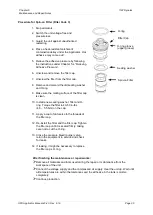
2. Loosen the lock nut (see illustration on next pages, under Chapter 5.5 Replacement of
the Built-in Filter) located on the top of the module.
3. Bottom the stroke adjustment screw lightly.
CAUTION
Tightening the stroke adjustment to shut OFF the nozzle will cause damage to the
Applicator.
4. Back off the screw one-half to one turn.
5. While holding the screw in position, tighten the lock nut.


