


Chapter 5
Maintenance and Repair Notes
ITW Dynatec
UFD Applicator, Manual 40-43, Rev. 6.16
Page 37
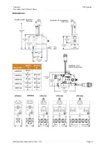
Module Assembly Instructions for the PN 104993 UFD Module
Demount the module from the service block, refer to the instructions in Chapter 5.6
Replacement of Standard Module on previous page.
Use the component illustration and parts list in Chapter 7 as a reference with the
following instructions for the PN 104993 UFD module.
ITW Dynatec has a Module Seal Kit available (PN 105150) which contains the
components necessary to rebuild one module, including the seal cartridge assembly, all
O-rings, spring and seal lubricant.
1. During re-assembly, coat all O-rings with a liberal amount of High Temp Lube (PN
N07588).
CAUTION
DO NOT SUBSTITUTE! Failure to use High Temp Lube (N07588) may result in
premature seal breakdown and leakage of glue from the Applicator!
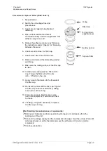
2. Insert the new seal cartridge assembly into the module body. (Note that there are two
holes in the seal cartridge cavity in the module body. One hole accepts the roll pin in
the seal cartridge. The other is an air hole which must line up with the air hole in the
seal cartridge.) Align the roll pin in the seal cartridge with the corresponding hole in the
top of the module body. Press the seal cartridge into position.
The air hole in the seal
cartridge must align with the air hole in the module body for the valve to
function properly.
3. Place a new piston O-ring onto the stem assembly and slowly insert the stem
assembly into the seal cartridge.
4. Place the new spring on top of the piston.
5. Loosen and back out the adjusting screw in the air cylinder. Place the air cylinder over
the spring and piston and press down into place. Take care not to dislodge the spring
or damage may result. Secure the air cylinder with the four mounting screws.
6. Place new O-rings on the seat assembly and insert the seat assembly into the bottom
of the module body. Secure with the four mounting screws. Spring resistance will be
felt as the screws are tightened. Tighten the screws evenly to avoid binding.
7. Place new O-rings into the grooves on the rear face of the module and mount the
module onto the service block.
8. Allow five minutes for the module to heat. Adjust the stem stroke to the desired
setting.
To disassemble, reverse above order.


