background image

 V 

10/04  

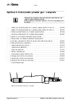
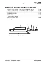
OptiGun 2-A(X) (GA02) Automatic powder gun 

Spare parts list  

  49 

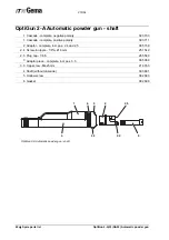
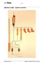
OptiGun 2-A(X) - system overview 

1  OptiGun 2-AX Automatic powder gun 

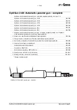
2  OptiGun 2-A Automatic powder gun - complete, with flat jet nozzle set, gun cable 

(20 m), parts set, cleaning brush, without SuperCorona, negative polarity 

393 568

  OptiGun 2-A Automatic powder gun - complete, with flat jet nozzle set, gun cable 

(20 m), parts set, cleaning brush, without SuperCorona, positive polarity 

393 576

3  SuperCorona - complete 

385 174

  Nozzle set - round jet nozzle (pos. 4 and 5) 

382 922

4  Electrode holder (round jet nozzle central electrode) 

382 914

#

5  Round jet nozzle  

378 518

#

6  Sleeve nut 

379 166

  Nozzle set - flat jet nozzle (pos. 7 and 8) 

1000 047

#

7  Electrode holder (flat jet nozzle) 

1000 055

#

8  Flat jet nozzle - NF08 

1000 049

#

9  Flat jet nozzle - NF04 (slot in round form) 

383 082

#

10  Flat jet nozzle - NF02 (without slot) 

384 887

#

11  Flat jet nozzle - NF03 (nozzle front part Ø 24 mm) 

383 058

#

12  Sleeve nut for pos. 11 

383 074

13  Deflector plate - Ø 16 mm (0,63 in) 

331 341

#

14  Deflector plate - Ø 24 mm (0,94 in) 

331 333

#

15  Deflector plate - Ø 32 mm (1,26 in) 

331 325

#

16  Deflector plate - Ø 50 mm (1,97 in) 

345 822

#

17  Deflector plate - Ø 70 mm (2,76 in) 

353 949

#

18  Extension - 150 mm (5,91 in) 

378 852

#

19  Extension - 300 mm (11,82 in) 

378 860

#

20  Angle nozzle - PA01-45° - complete (incl. round jet nozzle with deflector Ø 24 mm) 

390 232

21  Angle nozzle - PA01-60° - complete (incl. round jet nozzle with deflector Ø 24 mm) 

383 724

22  Angle nozzle - PA01-90° - complete (incl. round jet nozzle with deflector Ø 24 mm) 

383 520

#

 Wearing part 


Summary of Contents for GA2

Page 1: ...En Operating instructions and spare parts list OptiGun 2 A X GA02 Automatic powder gun 0102 II 2 D ...

Page 2: ... or registered trademarks of their respective holders Reference is made in this manual to different trademarks or registered trademarks Such references do not mean that the manufacturers concerned approve of or are bound in any form by this manual We have endeavored to retain the preferred spelling of the trademarks and registered trademarks of the copyright holders To the best of our knowledge an...

Page 3: ...y measures 10 About this manual 11 General information 11 Function description 13 Field of application 13 OptiGun 2 A X Automatic powder gun overview 13 Typical characteristics 13 Scope of delivery 14 Structure and function 15 OptiGun 2 A X Automatic powder gun 15 High voltage generation 16 Circuit 16 Powder flow and rinsing air 16 Spray nozzles 17 Flat jet nozzle with vented central electrode 17 ...

Page 4: ...tling procedure 28 Reassembling the powder gun 34 Repairing the powder gun 35 Powder hose connection 35 Cleaning the spray nozzles 36 Daily or after each shift 36 Weekly 36 Monthly 36 Cleaning the SuperCorona 36 Troubleshooting guide 37 General information 37 Spare parts list 39 Ordering spare parts 39 OptiGun 2 A Automatic powder gun complete 40 OptiGun 2 A Automatic powder gun gun body 41 OptiGu...

Page 5: ...ath or serious injury WARNING Improper use of the equipment could damage the machine or cause it to malfunction Possible consequences minor injuries or damage to equipment INFORMATION useful tips and other information Conformity of use 1 The OptiGun 2 A X GA02 Automatic powder gun is built to the latest specification and conforms to the recognized technical safety regulations It is designed for th...

Page 6: ...tationary electrostatic powder spraying equipment General information The powder spraying equipment from ITW Gema is designed with safety in mind and is built according to the latest technological specifications This equipment can be dangerous if it is not used for its specified purpose Consequently it should be noted that there exists a danger to life and limb of the user or third party a danger ...

Page 7: ...nsible for the safe operation of equipment ITW Gema is in no way responsible for any resulting damages Safety conscious working Each person responsible for the assembly start up operation service and repair of powder spraying equipment must have read and understood the operating instructions and the Safety regulations chapter The operator must ensure that the user has had the appropriate training ...

Page 8: ...n and commit the responsible personnel to this 8 Activities such as checking powder fluidization or checking the high voltage spray gun etc must be carried out with the powder spraying equipment switched on Notes on special types of hazard Power It is necessary to refer once more to the danger of life from high voltage current if the shut down procedures are not observed High voltage equipment mus...

Page 9: ...uipment are forbidden for safety reasons The powder spraying equipment should not be used if damaged the faulty part must be immediately replaced or repaired Only original ITW Gema replacement parts should be used Damage caused by other parts is not covered by guarantee Repairs must only be carried out by specialists or in ITW Gema workshops Unauthorized conversions and modifications may lead to i...

Page 10: ...ety only use accessories and attachments listed in the operating instructions The use of other parts can lead to risk of injury Only original ITW Gema replacement parts should be used 15 Repairs must only be carried out by specialists and under no circumstances should they be carried out in the operating area The former protection must not be reduced 16 Conditions leading to dangerous levels of du...

Page 11: ...anic powder coating material Safety requirements EN 60529 identical DIN 40050 IP Type protection contact foreign bodies and water protection for electrical equipment 2 EN 60 204 identical DIN VDE 0113 VDE regulations for the setting up of high voltage electrical machine tools and processing machines with nominal voltages up to 1000 V 3 VDE Association of German Engineers Regulations DIN VDE 0100 R...

Page 12: ...on work to be done by the customer must be carried out according to local regulations Before starting up the plant a check must be made that no foreign objects are in the booth or in the ducting input and exhaust air It must be observed that all components are grounded according to the local regulations before start up ...

Page 13: ...r the working with the OptiGun 2 A X GA02 Automatic powder gun It will safely guide you through the start up process and give you references and tips for the optimal use of your new powder coating sys tem Information about the function mode of the individual system components booth gun control unit manual gun or powder injector you will find in the corresponding enclosed documentations ...

Page 14: ......

Page 15: ...cal coating structure Typical characteristics The OptiGun 2 A X Automatic powder gun can be easily dismantled and is therefore maintenance and repair friendly Continuous tightly sealed gun body with separate channels for cascade and rinsing air Continuous guided powder tube self sealing Quickly dismantlable SuperCorona ring Powder tube coupling with quick release fastener Covered hose and cable du...

Page 16: ...tiGun 2 A X GA02 Automatic powder gun Easily dismantlable and cleanable SuperCorona Scope of delivery OptiGun 2 A X Automatic powder gun Flat jet nozzle with electrode holder Cable binder with Velcro closure Gun cleaning brush Parts set ...

Page 17: ...nction 15 Structure and function OptiGun 2 A X Automatic powder gun OptiGun 2 A X Automatic powder gun 1 Spray nozzle 5 Powder gun attachment 2 Sleeve nut 6 Powder tube 3 Shaft with removeable high volt age cascade 7 Clamping sleeve 4 SuperCorona ring 3 4 1 2 5 6 7 ...

Page 18: ... the required high voltage is attained at the end approx 100 kV The high voltage is now fed in the spray nozzle to the electrode e 4 c d e 11 High voltage generation Circuit The OptiGun 2 A X Automatic powder gun is switched on and off by the OptiTronic gun control unit The control unit allows also the adjustment of low voltage powder flow and rinsing air to the gun Powder flow and rinsing air The...

Page 19: ...manual Flat jet nozzle with vented central electrode Round jet nozzle with vented deflector and vented central electrode The vented deflector is used to give to the powder stream emerging from the gun the form of a powder cloud The powder is charged by the central electrode The high voltage which is created in the gun cascade is con ducted through the black contact ring of the nozzle holder to the...

Page 20: ......

Page 21: ...cade 12 stages Ignition protection Type A acc EN 50177 Type B Dimensions OptiGun 2 A X OptiGun 2 A weight 670 g 1 48 pounds 740 g 1 63 pounds with Super Corona ring OptiGun 2 AX weight depending on gun length Type A Systems corresponding to EN 50050 1986 with an energy limitation of 5 mJ In these systems the danger of an electric shock or explosive energy does not exist The OptiGun 2 A X Automatic...

Page 22: ......

Page 23: ... the OptiGun 2 A X Automatic powder gun 1 Rinsing air hose 4 Supplementary air hose 2 Powder hose 5 Conveying air hose 3 Powder gun cable 6 Injector Function check General information 1 The installed gun must be directed toward a grounded work piece in the coating booth All connections must be attached 2 Switch on the gun control unit see also the control unit operat ing instructions the gun start...

Page 24: ...ve the gun is ready for application If malfunctions take place the cause of the fault can be located by the corresponding troubleshooting guide Troubleshooting In the case of possible faults see chapter Troubleshooting guide Please consider also the control unit operating instructions ...

Page 25: ...stored 2 If working interruptions take place such as lunch time night etc the main compressed air supply is to be interrupted Setting powder output and powder cloud The powder output depends on the powder type and the adjusted total air volume see the OptiTronic control unit operating instructions Setting total air volume The total air volume is depending on the powder hose length the number of ho...

Page 26: ...lat jet nozzle or its extension can be moved slightly 4 Turn the flat jet nozzle to desired axis direction 5 Tighten the sleeve nut firmly again If round jet nozzles with air rinsed deflectors are used 6 Replace the deflector Ø 16 24 and 32 mm are supplied with the gun Rinsing the powder hose If lengthy downtimes take place the powder hose is to be cleaned from powder Observe the following steps 1...

Page 27: ...ily maintenance The OptiGun 2 A X Automatic powder gun must be cleaned daily and thoroughly see in addition the chapter Cleaning and repair Weekly maintenance The powder hopper and the injector must be cleaned once a week The powder hopper should be filled just before starting operation The grounding connections of the control module with the coating booth and the suspension device of the workpiec...

Page 28: ......

Page 29: ...tc exter nally 2 Check the gun for abrasion Weekly 1 Remove powder hose from connector 2 Remove the spray nozzle from the gun and clean it 3 Blow through the gun with compressed air from the connection in the direction of flow 4 Clean the gun tube with the gun brush provided 5 Blow through the gun again with compressed air 6 Reassemble the gun and connect it 7 Blow through the powder hose and clea...

Page 30: ... pollution It is only to be dismantled so far as the desired part is accessible Before dismantling the OptiGun 2 A X automatic powder gun the control unit must be switched off and the gun plug disconnected OptiGun 2 A X Automatic powder gun components 1 Shaft with cascade 4 Connector 2 Gasket 5 Hollow bolt 3 Intermediate piece Dismantling procedure OptiGun 2 A X Automatic powder gun 1 2 3 4 5 ...

Page 31: ...V 10 04 OptiGun 2 A X GA02 Automatic powder gun Cleaning and repair 29 Dismantling procedure cont ...

Page 32: ...V 10 04 30 Cleaning and repair OptiGun 2 A X GA02 Automatic powder gun Dismantling procedure cont ...

Page 33: ...V 10 04 OptiGun 2 A X GA02 Automatic powder gun Cleaning and repair 31 Dismantling procedure cont ...

Page 34: ...V 10 04 32 Cleaning and repair OptiGun 2 A X GA02 Automatic powder gun Dismantling procedure cont ...

Page 35: ...V 10 04 OptiGun 2 A X GA02 Automatic powder gun Cleaning and repair 33 Dismantling procedure cont OptiGun 2 A X Automatic powder gun with extension ...

Page 36: ...nt Reassembling the powder gun The reassembly of the OptiGun 2 A X Automatic powder gun is to be carried out in the reverse order to the procedure shown above It is to be noted that the powder tube is pushed in up to the stop Attention A good contact to the contact pin must be ensured Contact pin ...

Page 37: ...y pulling the locking ring back to the stop If tolerances devi ate powder can escape from the powder hose Therefore it is recom mended to use the tube connection 32 The tube connection 32 should be left on the powder hose 11 for as long as this is used that means if two sets of powder hoses are avail able the double number of tube connections 32 are required On plugging on make sure that the O rin...

Page 38: ...o the powder gun Weekly Remove the spray nozzles and clean inside with compressed air If pow der sinterings should have formed these are to be removed Monthly Check the spray nozzles for abrasion The flat jet nozzle is to be changed if The spray pattern is no longer a regular oval Deeper grooves are in the nozzle slot or even the wall thick ness is not longer visible The wedge of the electrode hol...

Page 39: ...r gun control unit is switched on the green lamp lights up and com pressed air is available Electronic board in Op tiTronic defective Send in for repair High voltage too low or not available Adjust high voltage on the control unit Gun cable gun plug or gun connection defec tive Test gun cable on an other OptiTronic unit High voltage cascade defect Send in powder gun shaft for repair Powder gun spr...

Page 40: ......

Page 41: ...no 203 386 1 piece Clamp Ø 18 15 mm When ordering cable or hose material the required length must also be given The spare part numbers of this yard meter ware is always marked with an The wear parts are always marked with a All dimensions of plastic hoses are specified with the external and inter nal diameter Example Ø 8 6 mm 8 mm outside diameter o d 6 mm inside diameter i d WARNING Only original...

Page 42: ...gative polarity 393 649 Powder gun body OptiGun 2 A complete positive polarity 393 657 2 Sleeve nut see Nozzle combinations spare parts list 3 Flat jet nozzle see Nozzle combinations spare parts list 4 Gun cable complete 20 m 65 61 ft see also Gun cable spare parts list 393 827 5 Parts set not shown consisting of 385 670 Cable binder with Velcro closure 303 070 Cylinder screw M8x50 mm 235 113 Cap ...

Page 43: ...arity see Shaft spare parts list 393 665 OptiGun 2 A shaft complete positive polarity see Shaft spare parts list 393 673 2 Powder tube complete 385 182 3 Powder gun attachment 382 817 4 Clamp sleeve 358 584 5 Hose connection complete 362 670 5 1 O ring for pos 5 not shown 232 670 Wearing part 1 3 2 4 281 18 5 OptiGun 2 A Automatic powder gun gun body ...

Page 44: ... complete positive polarity 393 711 2 Adaptor complete incl pos 2 4 and 2 5 385 158 2 4 Screw in nipple 1 8 a Ø 6 mm 251 542 2 5 Plug cap 1 8 a 265 560 3 Adaptor piece complete incl pos 3 3 385 069 3 3 Cap screw M4x5 mm 216 763 4 Shaft without cascade 393 681 5 Hollow screw 382 680 6 Gasket 382 698 1 6 3 3 3 2 2 5 2 4 5 4 OptiGun 2 A Automatic powder gun shaft ...

Page 45: ... 393 550 1 OptiGun 2 AX Automatic powder gun body complete negative polarity see OptiGun 2 AX Automatic powder gun gun body spare parts list 2 Sleeve nut see Nozzle combinations spare parts list 379 166 3 Flat jet nozzle complete see Nozzle combinations spare parts list 4 Gun cable complete 20 m 65 61 ft see also Gun cable spare parts list 393 827 5 Parts set not shown consisting of 385 662 Cable ...

Page 46: ... in 393 630 1 OptiGun 2 A shaft complete negative polarity see spare parts list Shaft 393 665 2 Powder tube complete incl pos 4 OptiGun 2 AX 1650 385 255 OptiGun 2 AX 1450 385 344 OptiGun 2 AX 1250 385 352 OptiGun 2 AX 1050 385 360 OptiGun 2 AX 850 385 379 OptiGun 2 AX 650 385 387 3 Extension tube OptiGun 2 AX 1650 384 682 OptiGun 2 AX 1450 385 441 OptiGun 2 AX 1250 385 450 OptiGun 2 AX 1050 385 4...

Page 47: ...r extension cable 206 504 Cable plug for extension cable 200 085 9 Cover tube 360 317 11 Countersunk head screw M2x4 mm 257 958 12 Cylinder screw M5x6 mm 263 907 13 O ring Ø 10 82x1 78 mm 232 556 14 O ring Ø 7 65x1 78 mm 232 564 15 O ring Ø 8 1x1 6 mm 263 818 21 Stuffing box PG7 with kink protection 208 426 22 Cable 3x0 75 mm shielded 104 892 23 Connecting plug 7 pin 200 085 Please indicate length...

Page 48: ... 5x1 mm 231 606 6 Round jet nozzle 378 518 7 Deflector plate Ø 16 mm 0 63 in 331 341 7 1 Deflector plate Ø 24 mm 0 94 in 331 333 7 2 Deflector plate Ø 32 mm 1 26 in 331 325 8 Extension 150 mm 5 91 in 378 852 8 1 Extension 300 mm 11 82 in 378 860 9 Electrode holder incl pos 5 round jet central electrode 382 914 Wearing part Further nozzle versions are described in the System overview spare parts li...

Page 49: ...th extension 300 mm L 515 mm 394 289 1 SuperCorona Ring complete retrofit set 391 980 SuperCorona Ring complete for version with extension 150 mm 394 173 SuperCorona Ring complete for version with extension 300 mm 394 203 5 Special screw 391 921 6 Cowl 384 372 6 1 Plug cap complete for pos 6 not shown 1001 037 7 Compression spring 0 4x2x10 9 mm 245 330 Wearing part 1 6 7 5 L OptiGun 2 A X Automati...

Page 50: ...V 10 04 48 Spare parts list OptiGun 2 A X GA02 Automatic powder gun OptiGun 2 A X system overview 14 13 7 4 16 17 15 12 11 10 5 6 1 9 8 2 3 18 19 20 21 22 ...

Page 51: ...t nozzle pos 7 and 8 1000 047 7 Electrode holder flat jet nozzle 1000 055 8 Flat jet nozzle NF08 1000 049 9 Flat jet nozzle NF04 slot in round form 383 082 10 Flat jet nozzle NF02 without slot 384 887 11 Flat jet nozzle NF03 nozzle front part Ø 24 mm 383 058 12 Sleeve nut for pos 11 383 074 13 Deflector plate Ø 16 mm 0 63 in 331 341 14 Deflector plate Ø 24 mm 0 94 in 331 333 15 Deflector plate Ø 3...

Reviews: