


V
05/10
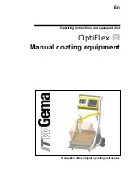
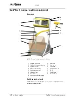
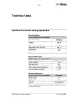
OptiFlex B manual coating equipment
Function description
13
Function description
Field of application
The OptiFlex B manual coating equipment (with powder box) is built ex-
clusively for electrostatic coating with organic powders. Any other use is
considered as non-conform. The manufacturer is not responsible for any
damage resulting from this; the risk for this is assumed by the user alone!
The OptiFlex B electrostatic powder manual coating equipment with the
OptiSelect manual powder gun is ideally suited for manual coating of ob-
jects in small series.
Typical characteristics
-
Processing the powder directly from the original powder
manufacturer's container
-
Total emptying of the powder container due to inclined
vibrating base
-
Quick and simple color change
-
Supplied ready for use
-
Available with one or two guns (extensible)


