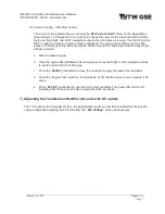
OM-2245 / Operation and Maintenance Manual
ITW GSE 4400 / 400 Hz. Generator Set
March 15, 2015
Chapter 2-4
Page 5
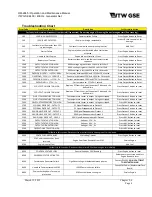
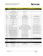
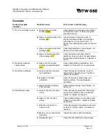
Error Code
2nd Corrective Action
3rd Corrective Action
4th Corrective Action
For faults in this section: Diconnect from Aircraft (if connected). Do not stop engine (if running). Do not let engine start (if not running).
100
200
Contact ITWGSE
300
Inspect fuel Sender wiring
Inspect fuel Sender
500
Check starter circuit to insure that it is
properly energized. (Replace Starter
Solenoid)
Replace Starter
600
Check fuel valve to ensure it is open.
Service Engine
700
Check battery cables
Charge Battery
Replace Battery
1000
Check voltage set-up value
Replace Control Board A1
Replace Interface Board A2
1100
Replace Control Board A1
Replace Interface Board A2
1200
Check voltage set-up value
Replace Control Board A1
Replace Interface Board A2
1300
Remove overload and re-engage
output
Replace Control Board A1
Replace Interface Board A2
1400
Remove overload and re-engage
output
Replace Control Board A1
Replace Interface Board A2
1500
Remove overload and re-engage
output
Replace Control Board A1
Replace Interface Board A2
1600
Remove overload and re-engage
output
Replace Control Board A1
Replace Interface Board A2
2000
Check set-up value
Remove load and check output cabling
Replace Control Boards A1 & A2
2100
Check set-up value
Remove load and check output cabling
Replace Control Boards A1 & A2
2200
Remove load and let plug cool down
Check connector / output cabling for any malfunction
Replace Control Boards A1 & A2
2300
Remove load and let plug cool down
Check connector / output cabling for any malfunction
Replace Control Boards A1 & A2
2400
Remove load and let plug cool down
Check connector / output cabling for any malfunction
Replace Control Boards A1 & A2
2700
Is output cable correctly inserted?
Check / correct installation
Replace Control Boards A1 & A2
2800
Is output cable correctly inserted?
Check / correct installation
Replace Control Boards A1 & A2
2900
Is output cable correctly inserted?
Check / correct installation
Replace Control Boards A1 & A2
3000
Is output cable correctly inserted?
Check / correct installation
Replace Control Boards A1 & A2
3100
Is output cable correctly inserted?
Check / correct installation
Replace Control Boards A1 & A2
3200
Check output voltage setup value
Check ARU Module and wiring
3300
Check output voltage setup value
Check ARU Module and wiring
3400
Check output voltage setup value
Check ARU Module and wiring
3500
Let the unit cool down and reset
Check airflow / air filters / fan
Check temp. sensor at rectifier heat
sink.
For faults in this section: Disconnect from aircraft. Shut down engine after cool down.
6000
Replace Control Board A1
6600
6700
Check Fuel sender unit.
For faults in this section: Disconnect from aircraft. Shut down engine immediately.
8000
Check Alternator
Check Battery
8200
Check emergency stop
Check user EPO (A2:X14)
Replace Control Board A1
8300
8400
Service Engine
8600


