OM-2245 / Operation and Maintenance Manual
ITW GSE 4400 / 400 Hz. Generator Set
March 15, 2015
Chapter 3-1
Page 1
Chapter 3
Overhaul/Major Repair
Section 1
Exciter Armature
1) General
This section provides information and instructions for removal and installation of the exciter armature
used on this generator set. Through design improvements, the exciter and rear main bearing can be
removed without removing the generator from the generator set. The name “exciter armature” refers to
the shaft-mounted, revolving, three-phase windings of the exciter.
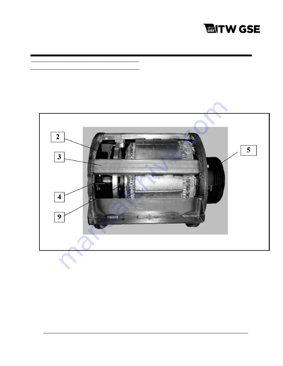
1. Coupling Key (Not Shown)
2. Flex Coupling Assembly
3. Generator Housing & Stator Assembly
4. Armature Assembly
5. Exciter Housing & Coils Assembly
6. Exciter Cover
7. Exciter Armature Assembly(Not Shown)
8. Exciter Key (Not Shown)
9. Front Bearing (Located Inside Housing Not
Shown)
10. Rear Bearing (Located In Exciter Housing Not
Shown).
Figure 3-1-1 General Assembly


