OM-2245 / Operation and Maintenance Manual
ITW GSE 4400 / 400 Hz. Generator Set
March 15, 2015
Chapter 3-2
Page 2
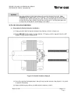
Access to Coupling Bolts
(for removal or installation)
Figure 3-2-2
b) Remove Coupling Assembly
WARNING
To prevent personal injury, keep fingers and hands clear of generator assembly until
the armature is block into place to prevent rotation.
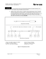
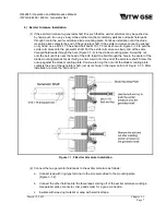
(1) Refer to Figure 3-2-3. Using a socket wrench, remove all three of the 3/8-16 bolts that secure the
bushing to the hub.
(2) Using a 3/16-inch Allen wrench, loosen the set-screw in the bushing to release pressure on the
key.
(3) To separate the bushing from the hub, lubricate two of the 3/8-16 bolts and insert them into the
two threaded holes in the bushing flange. With socket wrench, screw these bolts into the bushing
such that the bushing pops loose from the hub, alternating from bolt to bolt.
(4) When the bushing is loose in the hub, use a mallet to
GENTLY
tap the bushing out of the hub.
(5) Slide the coupling assembly off the shaft and remove the key.
(6) Inspect the coupling assembly components carefully as follows:
a
Check for deformed fan blades and damage to the disk.
b
Check the rubber exposed at both ends of the bushings for signs of deterioration.
c
Check hub and bushing for cracks, evidence of galling, fretting and rust pits. Light rust is
permissible on the bushing and the tapered bore of the hub.

