OM-2245 / Operation and Maintenance Manual
ITW GSE 4400 / 400 Hz. Generator Set
March 15, 2015
Chapter 3-3
Page 2
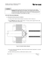
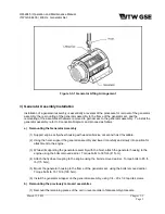
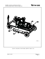
Figure 3-3-1 Generator Lifting Arrangement
3) Generator Assembly Installation
Installation of a generator assembly is essentially a reversal of the procedure for removal of the generator
assembly: the re-mounting of the generator assembly to the frame of the generator set, and the
remounting of the assemblies that were removed to gain access to the generator assembly. To install the
generator assembly, refer to Connection Diagram, and proceed as follows:
a) Remounting the Generator Assembly
(1) Support engine at flywheel housing with wooden blocks, or second hoist if available.
(2) Using the hoist, support the generator assembly and lower it carefully and slowly into position for
attachment to the engine.
(3) While still supporting the generator assembly with the hoist, attach the generator housing to the
engine using the bolts removed earlier. Torque bolts to 30 ft-lb (41 N-m).
(4) Attach the flywheel coupling to the engine using the bolts removed earlier. Torque bolts to 85 ft-
lb (115 N-m).
(5) Mount the generator housing to the frame of the generator set, using the bolts removed earlier.
Torque bolts to 73.7 ft-lb (100 N-m).
(6) Install the generator wrapper on the generator assembly, using 1/4 - 20 x 1/2 tap-tite screws.
b) Remounting the previously removed assemblies
(1) Remount the remaining pieces of the unit in reverse order of disassembly procedure.

