OM-2245 / Operation and Maintenance Manual
ITW GSE / Model ACE4400 / 400 Hz Generator Set
March 15, 2015
Chapter 4-2
Page 1
Section 2
Illustrated Parts List
1) Explanation of Parts List Arrangement
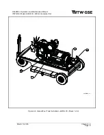
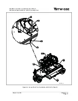
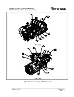
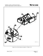
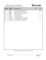
The parts list is arranged so that the illustration will appear on a left-hand page and the applicable parts
list will appear on the opposite right-hand page. Unless the list is unusually long, the user will be able to
look at the illustration and read the parts list without turning a page.
2) Symbols and Abbreviations
The following is a list of symbols and abbreviations used in the parts list:
*
-
Item not illustrated
#
-
Number or Part Number
A, or AMP
-
Ampere
AC
-
Alternating
current
AR
-
As
required
DC
-
Direct
current
DIA
Diameter
Deg
-
Degree
Fig
-
Figure
hd.
-
Head
hex
-
Hexagon
Hz
- Hertz
(cycles-per-second)
ID
- Inside
diameter
IN
- Inch
kVA
-
Kilovolt-ampere
lg
Long
uF
- Microfarad
No Number
Not supplied by Hobart
No.
-
Number
NHA
-
Next
higher
assembly
OD
Outside
Diameter
PRV
-
Peak
reverse
voltage
PSI
-
Pounds per square inch
Ref
-
Reference (the item has been listed previously)
RH
-
Right
Hand
LH
-
Left
Hand
TM
-
Technical
Manual
T-R
-
Transformer-rectifier
V
-
Volt or used as a prefix indicating vendor code
NOTE:
An item that does not reflect an index number is an assembly that is not illustrated in its
assembled state, or it is similar (right-hand, left-hand, top, etc.) to an item that is illustrated.
3) Hierarchy
Part Number
column lists the part number assigned. Sub- and /sub-assemblies are indicated by
indenture level (., .., …, etc.) to the component next higher assembly (NHA). Line items with no part
number assigned are listed as Non Applicable (No Number).


