OM-2245 / Operation and Maintenance Manual
ITW GSE 4400 / 400 Hz. Generator Set
March 15, 2015
Appendix A
Page 4
A-3-1 Standard wiring diagram
For service, maintenance and test purposes, the interlock system can be by-passed via the display setup. To
ensure personnel health and safety, the converter automatically returns into normal mode once it receives a
28 VDC voltage at terminal F2. (e.g. when the plug is connected to an aircraft.)
*This option requires a “split
-
F” co
nnector, which is typically a special order from most aircraft manufactures.
Note!
The 90% switch is by-passed by connecting te & 3
A.4
Operator’s Instruction
The 28 VDC ARU is operated by means of the Display / Keyboard Interface.
Please refer to Chapter 1-3 section 3 (ARU Operators Instructions).
A.5 Operating
the
unit
x
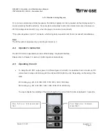
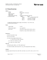
To adapt the 28 VDC output power to different types of aircraft, it is possible to set a maximum DC
current level in steps of 200 Amp (400 A unit) and 300 A (600 A unit). Depending on the rating of the
GPU:
400 A rating e.g. 200, 400, 600, 800, 1000, 1200, 1400, 1600 Amp
600 A rating e.g. 300, 600, 900, 1200, 1500, 1800, 2100, 2400 Amp
To ensure hassle-free starting of the aircraft engine, the current limit function is delayed 0.7 seconds.
Press
“Right arrow”
to increase
current limit.
Press
“Left arrow”
to decrease current
limit.

