OM-2245 / Operation and Maintenance Manual
ITW GSE 4400 / 400 Hz. Generator Set
March 15, 2015
Chapter 1-1
Page 12
e) Generator
The 400 Hz generator is a brushless, dual bearing, revolving field, three-phase, alternating current
type unit. The front end of the rotor shaft extends forward beyond the front bearing and is coupled to
the engine flywheel by a flexible coupling assembly. The rear end of the rotor shaft extends rearward
beyond the rear bearing and into the exciter stator housing. The exciter rotor is mounted on this shaft
extension with a key and is secured by a washer and 1/2-13 thread cap screw.
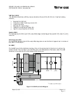
The rectifier has six diodes mounted on the exciter rotor and converts exciter AC output to DC for
excitation of the generator revolving fields. The exciter outputs DC to the generator fields, and
consequently the generator output, is controlled by the voltage regulator PC board (REG). A
centrifugal, radial-blade fan draws cooling air over all internal windings. Air enters at the exciter end
and is discharged at the drive end. The complete generator assembly is bolted to the engine’s
flywheel and housing.
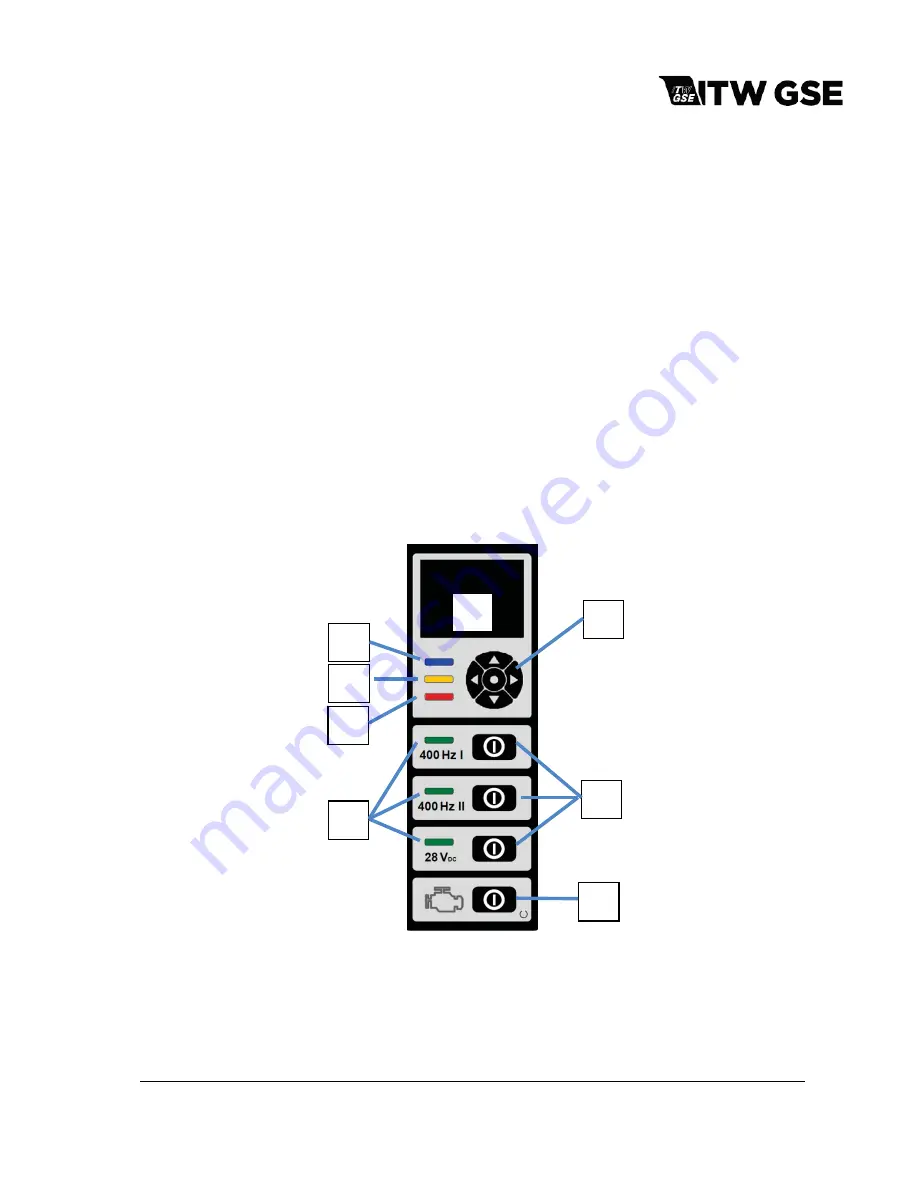
8) Operator Controls
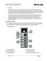
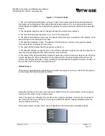
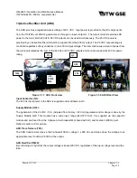
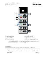
The control box is a protected enclosure on the right front panel of the GPU that has a modern graphical
display and easy to understand controls. The display allows the user to easily have access to all critical
operational information as well as providing textual descriptions of all warnings and failures.
a) Operator Controls
1.
LED Graphical Display
2.
Navigation Keypad
3.
Power ON "Blue" LED
4.
Warning "Amber" LED
5.
Alert/Failure "Red" LED
6.
Output ON "Green" LEDs
7.
Output ON/OFF (Reset)
8.
Power ON & Engine Start/Stop (Reset)
2
3
4
5
6
7
8
1

