OM-2245 / Operation and Maintenance Manual
ITW GSE 4400 / 400 Hz. Generator Set
March 15, 2015
Chapter 1-2
Page 4
(7) Tighten the clamp screws securely, but avoid damage to the cable insulation.
(8) Replace the canopy.
c) Installing the DC Output Cable (optional)
(1) Remove canopy. (While this may not be necessary, it greatly simplifies the process.)
(2) The DC output cable is not normally supplied unless specifically ordered. For normal aircraft
service, use cable assembly JB2840-30 (which meets Mil-C-7974D Assembly specification) with
30 feet of AWG 4/0 cables having a positive and negative connection.
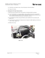
(3) The output cable is extended through the frame via the supplied hole in the cable tray. (See
Figure 1-2-3)
(4) The cables will be connected to the output bus bar located on the ARU assembly on the left rear
of the unit. (See Figure 1-2-6)
(5) Replace the canopy.
Figure 1-2-6

