OM-2245 / Operation and Maintenance Manual
ITW GSE 4400 / 400 Hz. Generator Set
March 15, 2015
Chapter 2-3
Page 5
4) Generator and Exciter Test
The generator fields and exciter stator may be tested with a Kelvin bridge. This is a double-bridge type
instrument required for the very low resistance’s encountered in this test. It is understood that zero (0)
resistance indicates a
SHORT CIRCUITED
condition. An infinite resistance reading indicates an
OPEN
CIRCUITED condition.
a) Disconnect generator stator leads at the back of the unit.
b) Disconnect the two black exciter field leads (Connector J6/P6) that is located under the back right
corner of the unit.
c) Check resistance and compare to values.
Test Connection
Resistance (Ohms)
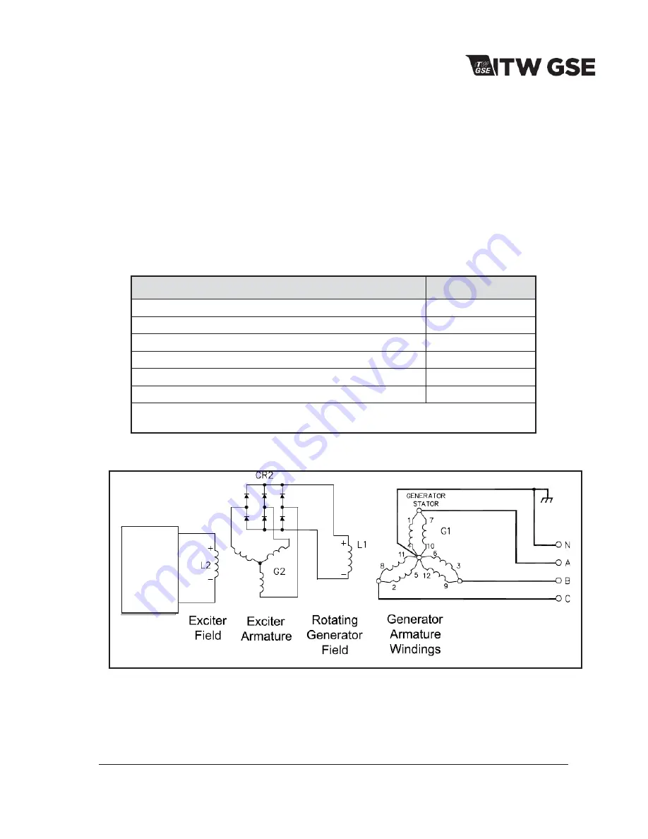
Generator Stator Phase A to N (G1)*
0.0026
Generator Stator Phase B to N (G1)*
0.0026
Generator Stator Phase C to N (G1)*
0.0026
Exciter Stator Field (L2)
29
A - B, B - C, C - A Exciter Armature (G2)
0.041
Generator Revolving Field (L1)
2.1
*NOTE:
The two leads of a phase must be connected when the test is made. Take
readings when the unit is cold and in an ambient temperature of 70 ºF (21ºC.).
Figure 2-1-8: Generator and Exciter Test Readings
Figure 2-3-9: Generator Connections
PC1
Interface
Board

