Set-up and assembly
ORBIMAT CA
| Operating instructions
20
orbitalum tools
GmbH, D-78224 Singen, www.orbitalum.com, Tel. +49 (0) 77 31 792-0
(09.03.15) OW_ORBIMAT_CA_BA_871060202_04_EN
7. SET-UP AND ASSEMBLY
7.1
Control elements
7.1.1
Overview of the main control elements
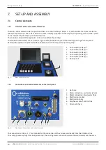
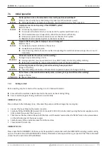
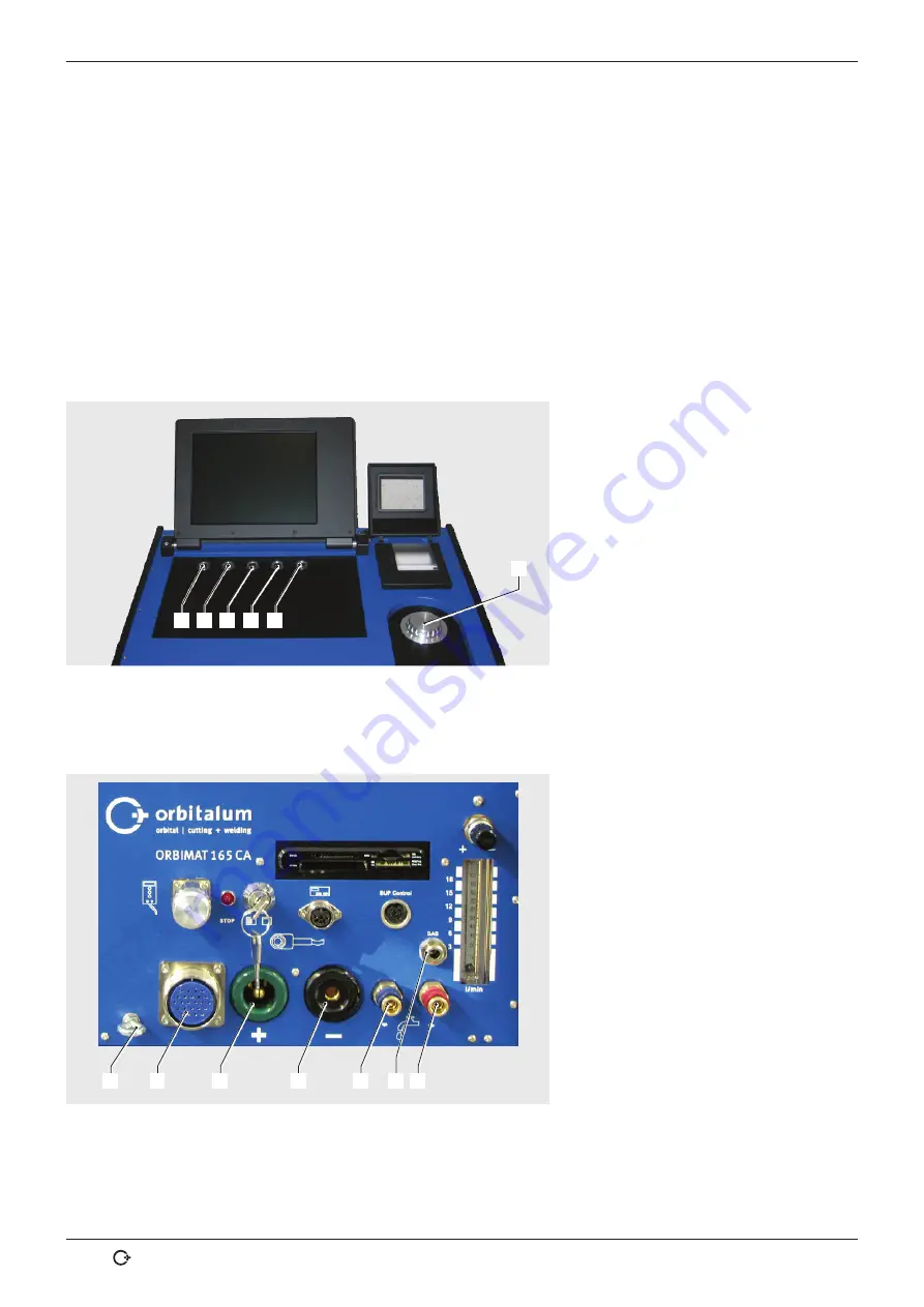
The main control elements are five push switches, so-called "softkeys" (Items 1–5) with variable functions located on
the top of the machine. The current function of these softkeys depends on the respective operating status of the system
and is indicated by the display on the bottom line.
The included standard PS2 keyboard can be set up before the softkeys.
The individual menu items are selected using the rotary knob (Item 6) and confirmed by pressing the rotary knob.
Detailed descriptions are provided with the explanation of the respective operating steps.
1
6
2
3
4
5
1. Push switch (softkey) 1
2. Push switch (softkey) 2
3. Push switch (softkey) 3
4. Push switch (softkey) 4
5. Push switch (softkey) 5
6. Rotary knob
Fig. 1:
Main control elements
7.1.2
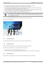
Connections and control elements on the front panel
7
2
6
5
4
3
1
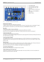
1. Gas hose
2. Water connection, red (water return)
3. Water connection, blue (water flow)
4. Weld current socket
5. Weld current plug
6. Amphenol socket, control line
7. Strain relief eye
Fig. 2:
Front panel: Connections and control elements
The connections at items 1 - 7 are intended for the connection of the various weld heads from the Orbitalum line.
The coding prevents plugs from being mixed up. The cooling water connections (water flow and return) are the same.

