Service and troubleshooting
ORBIMAT CA
| Operating instructions
74
orbitalum tools
GmbH, D-78224 Singen, www.orbitalum.com, Tel. +49 (0) 77 31 792-0
(09.03.15) OW_ORBIMAT_CA_BA_871060202_04_EN
9.4.1
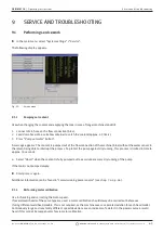
Meaning of the LEDs:
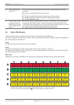
Row A (red)
These indicators are normally off.
LED lit up red: Control fuse defective.
The six control fuses are located on the interface PCB in the machine and are accessible after flipping open the cover.
They are arranged in a row and have the same enumeration as the LEDs. The LEDs in position 7 and 8 have no function.
A tripped control fuse normally indicates a defective switching power supply unit. An output-side overload of the
switching power supply unit is usually not present when a fuse is tripped, as all power supply units used are short-
circuit-proof and are also regulated automatically, even in the case of an overload.
Row B (green)
These indicators are normally on (except LED B2).
They indicate the status of the output voltages of the internal power supply units.
With a tripped fuse (row A), a LED of row B will not light up, because a power supply unit which is disconnected from the
mains by a fuse is no longer supplying output voltage.
If a green LED (except for B2) is off and no red LEDs are lit up, the power supply unit in question is overloaded on the
output side or is defective.
• B1: B1: Weld head power supply unit. The power supply unit provides power to the buttons in the handle of the
weld head, the limit switch (home position) and the head encoding with control voltage. If the voltage is missing,
the machine cannot be started. Usually, the "No weld head connected" error message appears, as head encoding
does not have a function.
• B2: Power supply unit of internal printer. This LED can also be off without there being an error. The power supply
unit is only switched on during printing.
–
Printer power supply unit control: Carry out printing with the internal printer.
– or –
From the main menu, select "
System settings
" > "
Service
" > "
Switch on internal printer
".
–
In both cases, the power supply unit is activated and the B2 LED lights up.
• B3: MOTOR power supply unit. The power supply unit provides operating voltage to the rotation motor and, if ap-
plicable, the motor of the cold wire supply unit
• B4: No function, lights up (internally bridged to B3).
• B5: PC controller power supply unit: The power supply provides voltage to the control computer. In case of a failure,
the system will not start, i.e. the display will remain dark.
• B6: Internal voltage. Control voltage is provided by the control computer for supplying purely internal consumers:
Sensors for gas, water, temperature and the key switch.
• B7: Internal control voltage of the inverter. No function; voltage is not used by the system at present.
• B8: Internal control voltage for supplying the red LEDs. If this voltage fails (LED off), any defective fuses in the (red)
row A of the LED indicator can no longer be indicated. Failure is improbable, as it is formed from multiple power
supply unit voltages.
Row C, D, E (yellow)
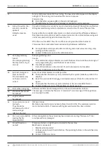
• C1: Key switch. LED lights up if the key switch is in "programming mode" (i.e. "long menu"). If the LED is not lit up,
the power supply unit (see LED B6) has failed or the key switch is defective..
• C2: Gas sensor. LED lights up if the gas sensor is reporting sufficient gas flow at the PC. Welding is not possible with-
out this signal. If the signal is not active shortly after the gas valve is opened, the gas quantity is still too low or the
sensor is defective. A defective sensor can be deactivated temporarily via the menu item "
System settings
" > "
System
adjustments
". Gas monitoring then no longer takes place. The switch-off is deactivated again the next time the entire
system is restarted.
• C3: Water sensor. LED flashes when the water pump is switched on and cooling water is flowing. Fan wheel sensor
which supplies one pulse per unit of water flow volume. The pulse frequency is therefore measured proportionally to
the water quantity so that it can be recorded, calculated and ultimately displayed by the system. If the LED does not
flash, the "
Cooling water problem
" message appears. The cause could be a defective pump, a "clogged" water circuit,
a defective pump power supply unit or a defective sensor. A defective sensor can be deactivated temporarily via the
menu item "
System settings
" > "
System adjustments
". Water monitoring then no longer takes place. The switch-off is

