background image

ThunderION2ThunderIONIQ2_UM_9752160050_NL_D_GB_F_V2_7


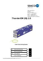
ThunderION (IQ) 2.0  


Static Neutralising System


SIMCO (Nederland) B.V. 
Postbus 71 
NL-7240 AB Lochem 

Telefoon  +31

-

(0)573

-

288333 

Telefax 

+31

-

(0)573

-

257319 

E-mail 

cs@simco-ion.nl 

Internet 

http://www.simco-ion.nl 

Handelsregister Apeldoorn Nr. 08046136 

NL 

Gebruikershandleiding 

Bedienungsanleitung 

GB  

User's Manual 

Notice d'utilisation 

31 

61 

90 

Summary of Contents for Simco-Ion ThunderION 2.0

Page 1: ...System SIMCO Nederland B V Postbus 71 NL 7240 AB Lochem Telefoon 31 0 573 288333 Telefax 31 0 573 257319 E mail cs simco ion nl Internet http www simco ion nl Handelsregister Apeldoorn Nr 08046136 NL Gebruikershandleiding D Bedienungsanleitung GB User s Manual F Notice d utilisation 1 31 61 90 ...

Page 2: ...ck met sensor IQ Easy nog niet beschikbaar 18 6 2 2 3 Sensor staaf meetwaarden koppelen 19 6 2 3 Ionisatiestaaf Standby Actief en autorun instellen 19 6 2 4 Ionisatiestaaf Information parameters expert mode 20 6 2 5 HV output frequency parameter aanpassen expert mode 20 6 2 6 Remote on off schakelen van de staaf via de remote on off ingang op de manager of via fieldbus expert mode 20 6 2 7 Datalog...

Page 3: ...an statische elektriciteit Waar het woord staaf of ThunderION in deze handleiding wordt gebruikt wordt in alle gevallen verwezen naar de ThunderION 2 reeks standaard of IQ versies Verklaring gebruikte symbolen Waarschuwing Wijst op speciale informatie om letsels of aanzienlijke schade aan het product of het milieu te voorkomen Gevaar Wijst op informatie om elektrische schokken te vermijden Opmerki...

Page 4: ...4V omgezet in positieve en negatieve hoogspanning De hoogspanning genereert een elektrisch veld op de emitters van de ionisatiestaaf waardoor de luchtmoleculen rond de emitters in positieve en negatieve ionen worden omgezet Wanneer elektrostatisch geladen materiaal in de buurt van de staaf komt worden er elektronen uitgewisseld totdat het materiaal neutraal is Afbeelding 1 ThunderION Steun Emitter...

Page 5: ...ervangbare delen zorgen ervoor dat de staaf gemakkelijker sneller en comfortabeler kan worden schoongemaakt De staaf werkt standaard met een pulsfrequentie van 5 Hz Deze pulsfrequentie wordt gebruikt om afwisselend positieve en negatieve ionen te produceren Voor speciale toepassingen kan deze pulsfrequentie worden aangepast om aan optimale ontladingsresultaten te komen Via een Manager IQ Easy kunn...

Page 6: ... Hoogspanning is gevaarlijk voor dragers van een pacemaker De hoogspanningsemitters 30 kV zijn stroombegrensd op 150 µA wat betekent dat ze aanraakveilig zijn Wanneer iemand in de buurt van een emitter komt of met een emitter contact maakt op een polariteit kan dit als gevolg hebben dat die persoon elektrostatisch geladen wordt en een schokreactie krijgt wanneer deze persoon ontlaadt op andere gea...

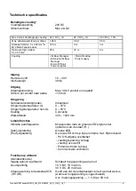
Page 7: ...V DC 25 mA max Uitgang werking ionisatiestaaf OK HV OK Geeft aan dat de ionisatiestaaf correct aan het werk is wanneer hoogspanning is ingeschakeld Uo Voedingsspanning 1 V Max 50 mA Max totale kabellengte voeding 24 V DC 2 24 V DC 5 24 V DC 10 Max kabelelweerstand per draad 1 26 Ω 0 9 Ω 0 3 Ω Standaard Simco 5 x 0 34 mm M12 Male Female kabel 12 5 m 9 m 3 m Optionele Simco kabel 5 x 0 75 mm 25 m 18...

Page 8: ... tot 5125 mm Afmetingen BxHxL 61 mm x 114 mm x totale lengte Eff Lengte 195 mm Gewicht 0 8 kg 2 4 kg m Behuizing Kunststof Emitter metalen deel Speciale legering Emitter kunststof deel Siliconen of PTFE Montagemateriaal Montagebeugels De voeding moet een begrensde voeding of voeding met NEC klasse 2 zijn De uitgang van de voeding moet correct geaard zijn Zie H5 6 2 Een LPS gecertificeerde voeding ...

Page 9: ...ThunderION2ThunderIONIQ2_UM_9752160050_NL_D_GB_F_V2_7 8 Afbeelding 2 Afmetingen ThunderION met 3 emitters Afbeelding 3 ThunderION met 4 emitters screw connection Afbeelding 4 Optionele aansluitingen ...

Page 10: ...n zie H5 6 2 De ionisatiestaaf kan gevoed worden door een al beschikbare 24 V DC voeding op de machine indien deze aan bovenstaande eisen voldoet maar ook met een voedingsapparaat van Simco Ion Netherlands Door Simco Ion Netherlands aanbevolen voedingsapparaten Onderdeelnummer Beschrijving 4524001000 Desktop 100 240 V ACnaar 24 V DC voor 1 ThunderION IP40 4510001400 Besturingsmodule voor max 4 Thu...

Page 11: ...tot geleidende machineonderdelen houden Gebruik de meegeleverde montagebeugels Monteer de ionisatiestaaf Recht tegenover de plaats waar statische elektriciteit problemen veroorzaakt Met de emitters gericht in de richting van het materiaal dat geneutraliseerd moet worden Op plaatsen waar het materiaal geneutraliseerd is moet er een laag lucht onder zitten De correcte afstand van de ionisatiestaaf t...

Page 12: ...ThunderION2ThunderIONIQ2_UM_9752160050_NL_D_GB_F_V2_7 11 NL Afbeelding 5 Afbeelding 6 ...

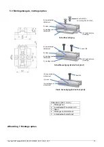
Page 13: ...ng 7 Montage opties 2 x schroef M5 2 x sluitring M5 ISO 1441 richtingindicatoren montage 3 steun 4 montagevoet sluitschroef 5 Ionisatiestaaf sluitschroef 3 steun 4 montagevoet sluitschroef 1 montagevoet richtingindicatoren montage 2 x bout M5 5 Ionisatiestaaf sluitschroef Bout M5 5 Ionisatiestaaf sluitschroef 3 steun 4 montagevoet sluitschroef Schuifbevestiging Schuifbevestiging kleine foot print ...

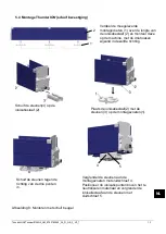
Page 14: ...eze op de machine met de driehoeken wijzend in dezelfde richting Schuif de steunen 3 op de ionisatiestaaf 2 Plaats de ionisatiestaaf 2 met de steunen 3 op de montagevoeten 1 Schuif de steunen tegen de richting van de drie punten in Vergrendel de steunen aan de montagevoeten met sluitschroef 4 Positioneer de ionisatiepunten boven het te neutraliseren materiaal en vergrendel de ionisatiestaaf aan de...

Page 15: ...p voeding Sluit de externe geel groene kabel aan op het aardingsgedeelte van de machine Sluit de kabel met de M12 connector van de desktop voeding aan op de ionisatiestaaf Sluit de voedingskabel aan 4 Ontkoppel de M12 connector aan de zijkant van de ionisatiestaaf Draai de sluitschroeven 4 van de beugels los Schuif de ionisatiestaaf met de beugel van de montagevoeten af in de richting van de drieh...

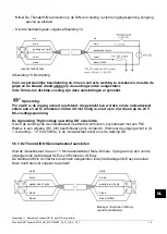
Page 16: ...dien dit niet nodig is sluit u pin 2 wit aan op de 24 V DC voedingsspanning De signalering High voltage operating OK aansluiten U kunt de werking van de ionisatiestaaf op afstand controleren bijvoorbeeld met een PLC Hiertoe is een uitgang HV_OK beschikbaar op de connector Wanneer de uitgang actief is U U voeding 1V max 50mA is de ionisatiestaaf actief en is de werking OK 5 6 3 De ThunderION IQ ion...

Page 17: ...ng actief gemaakt wordt zal de ionisatiestaaf ingeschakeld worden Bij een door Simco Ion geleverde desktopvoeding is de Remote on off intern al verbonden met de 24 V voedingsspanning Wanneer deze voeding gebruikt wordt zal de ionisatiestaaf dus direct inschakelen zodra de voeding wordt ingeschakeld 6 2ThunderION IQ in gebruik nemen via het IQ Easy Platform Indien een Undefined param in de infosche...

Page 18: ...rt De ionisatiestaaf kent 4 operation modes 1 Fixed De ionisatiestaaf heeft een vast ingestelde ionisatie De ionisatie functioneert als een ThunderION 2 0 Er worden een vast aantal positieve en negatieve ionen geproduceerd Afhankelijk van de applicatie zal de statische lading geneutraliseerd worden en zal er een restspanning lading achterblijven 2 Manual Voor test doeleinden of voor zeer specifiek...

Page 19: ...met de slider of met de knop richting 100 te gaan worden er steeds meer negatieve ionen geproduceerd om positieve lading te neutraliseren Richting 100 meer positieve om negatieve lading te neutraliseren Let op de ionen eindbalans kan worden verstoord indien een te extreme instelling wordt gekozen n x HV balance offset schuif met de slider of met naar de gewenste waarde en bevestig met De ionisatie...

Page 20: ...segments Selecteer de segmenten die uit gezet moeten worden Bevestig de keuze met De ionisatiestaaf zal nu het gemiddelde avg van de enabled segmenten laten zien in de parameters en de Graphics Tab en gebruiken voor de regeling nog niet beschikbaar Ionisatiestaaf Standby Actief en autorun instellen Standaard zal de staaf actief worden nadat alle informatie door de manager is verzameld doordat de p...

Page 21: ... 5 Hz maar kan in specifieke gevallen op een andere waarde ingesteld worden n x HV output frequencyl schuif met de slider of met naar de gewenste waarde en bevestig met Remote on off schakelen van de staaf via de remote on off ingang op de manager of via fieldbus expert mode Indien gewenst kan de staaf aan uit worden geschakeld met de remote on off ingang van de Manager of door een instructie van ...

Page 22: ...seerd 7 2Controle op de werking via de LED s De kleur van de status LED s op de ionisatiestaaf geven de status van de ionisatiestaaf aan Indien de LED s na het opstarten continu rood oplichten betekent dit dat de ionisatiestaaf hoogspanning overbelast wordt zie 7 5 en H9 7 2 1 Controle op de werking via de LED s ThunderION Tijdens het opstarten van de staaf 2 seconden snel groen knipperend Tabel 1...

Page 23: ...rmen zal men via de achtergrondkleur achter het symbool altijd de status van de ionisatiestaaf kunnen zien Groen stand by blauw running OK oranje warning rood alarm Detail info wordt gegeven in de Information Graphics Action log en Datalog Tab 7 4 1 Information tab Met de buttons kunt u door de verschillende pagina s bladeren Gegevens over de werking die u hier kunt vinden Ionisation current uA hi...

Page 24: ...p voor stap een veranderde status van de staaf gelogd Dit wordt aangegeven met datum en tijd waarop de statusverandering heeft plaatsgevonden Belangrijkste meldingen REMOTE ON HV OK de staaf is aangezet en functioneert OK REMOTE OFF HV NOT OK de staaf is uitgezet dus de hoogspanning is niet OK 7 4 4 Data log tab In de Data log tab wordt op vaste tijden alle beschikbare meet data van de ionisatiest...

Page 25: ...onmaken moet u het zwarte montageoppervlak van de emitters en de rest van de behuizing ook de externe oppervlakken schoonmaken Voor het gemakkelijk schoonmaken kunnen de zijpanelen steun en eindplaten gemakkelijk worden losgeklikt De emitters kunnen verwijderd worden om separaat te reinigen of te vervangen Na verwijdering van de emitter moet u ervoor zorgen dat er geen schoonmaakproduct of vervuil...

Page 26: ...0243 afdichtings ring schroefdraad Met afdichtingsring Losdraaien aan de electrode isolator Afbeelding 12 Zonder afdichtingsring Trek de electrode isolator loodrecht van de ionisatiestaaf af Emitter pull 4509001030 serienummer 13470001 t m 14450243 Afbeelding 13 Met afdichtingsring Losdraaien aan de electrode isolator Emitter PTFE screw 4509001037 Voor Thunderion 2 0 UL bar Afbeelding 14 afdichtin...

Page 27: ...0_NL_D_GB_F_V2_7 26 Ionisatiestaaf met beschermende afdekkingen Beschermings plug Afbeelding 16 Afbeelding 17 Art nr 9290090060 Positie waar de electrode isolator vastgehouden moet worden om de emitter te demonteren monteren Afbeelding 15 ...

Page 28: ...e Geen minder hoogspanning op emitters Staaf te dicht bij geleidende onderdelen geplaatst Verplaats de ionisatiestaaf HV OK niet actief extern Staaf is zeer vuil Maak de ionisatiestaaf schoon Ionisatiestaaf foutief Retourneer de ionisatiestaaf Rood knipperend Interne hardwarefout Voedingsspanning te laag Controleer de voedingsspanning en de kabellengte Interne temp te hoog Omg Temp 50 C of ionisat...

Page 29: ...rd Ionisatiestaaf opnieuw positioneren zie H 5 2 Emitters zijn afgedekt Afdekking verwijderen LED s op ionisatiestaaf knipperen rood 1 Hz Wel hoogspanning aan de emitters Hoogspanning te laag Voedingsspanning te laag Controleer 24VDC manager of vergroot diameter aansluitleiding of kort de aansluitkabel in Interne temperatuur te hoog Controleer op metalen delen dicht bij de staaf LED s op ionisatie...

Page 30: ...end bestaat het gevaar dat onderdelen onder gevaarlijke spanning worden aangeraakt Neem bij problemen contact op met Simco Ion of met de agent in uw regio Simco Ion raadt u aan voor reparaties de apparatuur retour te zenden Volg de procedure op www simco ion nl repair Verpak de apparatuur deugdelijk en vermeld duidelijk de reden van retour 11 Afdanken Respecteer de plaatselijke milieuvoorschriften...

Page 31: ... 7519020365 kabel met 5 geleiders met rechte M12 connector 5 m 10b 7519020366 kabel met 5 geleiders met rechte M12 connector 10 m 11a 7519020375 kabel met 5 geleiders met haakse M12 connector 5 m 11b 7519020376 kabel met 5 geleiders met haakse M12 connector 10 m 12 7519020435 DIN rail voeding 100 240 V AC naar 24 V DC 10A 13 7519020425 DIN rail voeding 100 240 V AC naar 24 V DC 4A 14 7519020430 DI...

Page 32: ...8 6 2 2 3 Messwerte Sensorstab koppeln 488 6 2 3 Ionensprühstab Stand by Aktiv und autorun festlegen 498 6 2 4 Informationsparameter Ionensprühstab Modus Experte expert mode 49 6 2 5 Parameter HS Ausgangsfrequenz ändern Modus Experte expert mode 49 6 2 6 Stab über den Remote An Aus Eingang des Managers oder über Feldbus per Remote Schaltung ein bzw ausschalten Modus Experte expert mode 50 6 2 7 Da...

Page 33: ...derION Bei Verwendung des Begriffes Stab oder ThunderION in dieser Bedienungsanleitung bezieht sich dies stets auf die ThunderION 2 Reihe Standard bzw IQ Ausführung Erklärung der verwendeten Symbole Warnung Besondere Anweisungen zur Verhinderung von Verletzungen bzw erheblichen Schäden am Gerät oder an der Umwelt Gefahr Informationen zur Vermeidung von Stromschlägen Hinweis Wichtige Informationen ...

Page 34: ...versorgung erfolgen Die Betriebsspannung von 24 V DC wird im Stab in eine positive und negative Hochspannung umgewandelt Die Hochspannung erzeugt an den Emittern des Ionensprühstabes ein elektrisches Feld wodurch die Luftmoleküle rund um die Emitter in positive und negative Ionen aufgespalten werden Wenn elektrostatisch geladenes Material in die Nähe des Stabes gelangt findet ein Elektronenaustaus...

Page 35: ...ind ebenfalls austauschbar Die austauschbaren Bauteile ermöglichen eine einfachere schnellere und bequemere Reinigung des Stabes Standardmäßig arbeitet der Stab mit einer Impulsfrequenz von 5 Hz Diese Impulsfrequenz dient der abwechselnden Erzeugung von positiven und negativen Ionen Bei speziellen Anwendungen muss diese Impulsfrequenz für optimale Entladungsergebnisse abgestimmt werden Über den Ma...

Page 36: ...achern eine Gefahr dar Die unter Hochspannung stehenden Emitter 30 kV sind auf eine Stromstärke von 150 µA beschränkt wodurch sie berührungssicher sind und nicht die Gefahr eines elektrischen Schlages besteht Personen die sich in der Nähe eines Emitters einer Polarität aufhalten oder diesen berühren werden eventuell elektrostatisch aufgeladen und erhalten einen elektrischen Schlag wenn sie sich an...

Page 37: ...nung 300 1000 mm Lokale Funktionen Anzeige der Impulsfrequenzeinstellung Blinkende rote und grüne LEDs beim Einschalten des Stabes Anzeige Ein Grüne LED Anzeige Fehler Die rote LED leuchtet bei internen Fehlern z B HV OK Ausgang überlastet Versorgungsspannung zu niedrig Gerät überhitzt Primärstrom zu hoch Kommunikation abgebrochen Fernbedienungs funktionen Standardausführung Max Gesamtlänge des Ka...

Page 38: ...ngspegel siehe Bedienungsanleitung IQ Easy Manager Mechanisch Effektive Stablänge 250 mm bis 5125 mm Abmessungen BxHxL 61 mm x 114 mm x Gesamtlänge effektive Länge 195 mm Gewicht 0 8 kg 2 4 kg m Gehäuse Emitter Emitterhalter Kunststoff Sonderlegierung Silikon oder PTFE Montagemittel Montagebügel Die Stromversorgung darf nur über eine geerdete Limited Power Supply LPS oder ein NEC Klasse 2 Netzteil...

Page 39: ...t eine sichere Ausgangsspannung Legen Sie nur die angegebenen Spannungen an die Schaltungen an Die 0 V des Betriebsspannungsausgangs müssen ordnungsgemäß geerdet sein siehe Abschnitt 5 2 3 Der Ionensprühstab kann durch ein bereits vorhandenes 24 V Gleichstromnetzteil an der Maschine bei Erfüllung der oben genannten Anforderungen oder durch ein von Simco Ion Netherlands geliefertes Netzteil versorg...

Page 40: ...für optimale Ergebnisse nicht eingehalten werden können muss ein Mindestabstand von 50 mm von der Seite des Stabes zu elektrisch leitfähigen Maschinenteilen eingehalten werden Verwenden Sie die mitgelieferten Montagebügel Montieren Sie den Ionensprühstab Genau vor der Stelle an der statische Elektrizität Probleme verursacht Mit den Emittern in Richtung auf das zu neutralisierende Material Die Stel...

Page 41: ...ThunderION2ThunderIONIQ2_UM_9752160050_NL_D_GB_F_V2_7 40 Abbildung 5 Abbildung 6 ...

Page 42: ...IONIQ2_UM_9752160050_NL_D_GB_F_V2_7 41 D 5 2 Halterungsstangen Montageoptionen Einzelteile Abb 7 8 und 9 1 Montagefuß 2 Ionensprühstab Thunderion 2 0 3 Schlitten 4 Montagefuß festschrauben 5 Ionensprühstab festschrauben ...

Page 43: ... diese mit den Haken in die gleiche Richtung zeigend an der Maschine montieren Die Schlitten 3 auf den Ionensprühstab 2 schieben Den Ionensprühstab 2 mit den Schlitten 3 auf die Montagefüße 1 montieren 2 1 Die Schlitten in Richtung gegen die Haken auf die Füße aufschieben Die Schlitten an den Füßen mittels Schraube 4 verriegeln Den Stab gegenüber dem zu entladenden material positionieren und mit d...

Page 44: ...gefüßen an und schieben Sie die gesamte Baugruppe in Richtung der drei Dreiecke Montagemethode 5 Verriegeln Sie den Ionensprühstab in den Montagefüßen indem Sie die Stellschrauben Nr 5 in die Halterung drehen Sie sollten zumindest die zwei äußeren Halterungen verriegeln 6 Schließen Sie den Ionensprühstab gemäß Abschnitt 5 6 an Stellen Sie sicher dass das Kabel auf eine sichere Weise zur Stromverso...

Page 45: ...gen bereits hergestellt Hinweis Stift 2 weiß ist der Fernbedienungseingang und kann zum externen Ein Ausschalten des Ionensprühstabes verwendet werden Wird Pin 2 weiß nicht verwendet schließen Sie diesen an die 24V DC Betriebsspannung an Hochspannungsbetrieb OK Signal anschließen Die Funktion des Ionensprühstabes kann beispielsweise mittels SPS aus der Ferne überwacht werden Zu diesem Zweck steht ...

Page 46: ...ochspannung aktiv ist HS O K siehe Abbildung 10 Schalten Sie die Spannungsversorgung des Ionensprühstabs ein Legen Sie 24 V DC an den Remote An Aus Eingang des Stabs an Sobald die 24 V DC Versorgungsspannung angelegt und der Remote An Aus Eingang aktiviert wird wird der Ionensprühstab eingeschaltet Bei einem von Simco Ion gelieferten Tischnetzteil ist der Remote An Aus Eingang bereits intern mit d...

Page 47: ...de Zum Festlegen aller Parameter und zur Durchführung von Wartungsarbeiten müssen Sie über die Benutzerechte der Benutzerebene Experte verfügen Zur Anmeldung ist gegebenenfalls ein Kennwort erforderlich Für eine ausführliche Beschreibung siehe Abschnitt 6 4 der Bedienungsanleitung des Manager IQ Easy Nach Anmeldung auf dieser Benutzerebene bleiben Sie bis zur Anmeldung auf einer anderen Benutzereb...

Page 48: ...itiv 3 Geschlossener Regelkreis CLFB Closed Loop FeedBack noch nicht verfügbar Für diesen Modus muss ein Sensor bar IQ Easy an die Plattform angeschlossen sein Nachdem die Folie oder das zu neutralisierende Objekt den ThunderION IQ passiert hat misst der Sensor die Restladung Dieser Wert wird an den Ionensprühstab übermittelt der daraufhin mit dem Ziel die Restladung so weit wie möglich zu verring...

Page 49: ...ng fortgesetzt 6 2 2 2 Betriebsmodus Geschlossener Regelkreis CLFB Closed Loop FeedBack mit Sensor IQ Easy noch nicht verfügbar Nach Auswahl des Betriebsmodus CLFB muss zur Verwendung der Messwerte zur Reglung ein Sensor gekoppelt werden Zum Koppeln eines Sensors siehe Abschnitt 6 2 2 3 6 2 2 3 Messwerte Sensorstab koppeln Der Sensorstab muss mit dem ThunderION IQ gekoppelt werden Blättern Sie mit...

Page 50: ...Spannungsunterbrechung oder Trennung nicht automatisch aktiviert werden muss der Autostart autorun Parameter im Modus Experte auf Nein No geändert werden 6 2 n x Autostart Autorun No 6 2 4 Informationsparameter Ionensprühstab Modus Experte expert mode Um die verschiedenen Geräte besser identifizieren zu können können nach Bedarf verschiedene Informationsparameter eingetragen werden Ändern Sie sofe...

Page 51: ... Kontinuierlich Continous auf Remote oder Feldbus Fieldbus geändert werden n x Remote An Aus Quelle Remote on off source wählen Sie Remote oder Feldbus Fieldbus 6 2 7 Datenprotokollierung de aktiveren Falls gewünscht kann der Manager Daten über den Betrieb des Stabs protokollieren Zur De aktivierung dieser Protokollierung muss der Parameter Datenprotokollierung Datalogging geändert werden Für eine...

Page 52: ...deutet dies dass der Ionensprühstab Hochspannung überlastet wird siehe 7 5 und Kapitel 9 7 2 1 Funktionsüberprüfung über LEDs ThunderION Während des Startvorgangs des Stabs 2 Sekunden schnelles Blinken grün Tabelle 1 Übersicht Statusanzeige Ionensprühstab Standardausführung nicht IQ Funktion LED am Stab ThunderION In Bereitschaft Blinkt grün 1Hz In Betrieb Leuchtet grün Überlastet Leuchtet rot Aus...

Page 53: ...ieb O K orange Warnung rot Alarm Ausführliche Informationen werden unter den Registerkarten Informationen Information Grafiken Graphics Ereignisprotokoll Action log und Daten Protokoll Data log angezeigt 7 4 1 Registerkarte Informationen Information Mit den Schaltflächen können Sie durch die verschiedenen Seiten blättern Hier finden Sie folgende Funktionsdaten Ionisationsstrom uA Ionisation curren...

Page 54: ... wird schrittweise die Änderung des Status des Stabs protokolliert Statusänderungen werden mit dem Datum und der Zeit angezeigt an denen die Änderung erfolgte Wichtigste Meldungen REMOTE EIN HS O K REMOTE ON HV OK Der Stab ist eingeschaltet und funktioniert ordnungsgemäß REMOTE AUS HS NICHT O K REMOTE OFF HV NOT OK Der Stab ist abgeschaltet und somit ist die Hochspannung nicht O K 7 4 4 Registerka...

Page 55: ...ollständig trocken Bei hartnäckigen Verschmutzungen kann auch Veconova 10 als Reinigungsmittel verwendet werden www eco nova nl Reinigen Sie im Rahen der Reinigung die schwarze Montagefläche der Emitter sowie das übrige Gehäuse und die Außenflächen Zur einfachen Reinigung können die Seitenwände Stütze und Endplatten leicht abgenommen werden Die Emitter können zwecks separater Reinigung oder Austau...

Page 56: ...ichtungsring Gewinde Mit Dichtungsring Am Elektrodenisolator lösen Abbildung 12 Ohne Dichtungsring Den Elektrodenisolator gerade vom Ionensprühstab abziehen Emitter zum Abziehen 4509001030 Seriennummer 13470001 bis 14450243 Abbildung 13 Met afdichtingsring Losdraaien aan de electrode isolator Emitter PTFE screw 4509001037 Voor Thunderion 2 0 UL bar schroefdraad Abbildung 14 afdichtings ring ...

Page 57: ...9752160050_NL_D_GB_F_V2_7 56 Stelle an der der Elektrodenisolator zwecks Montage Demontage festgehalten werden muss Ionensprühstab mit Schutzabdeckungen Schutzabdeckungen Abbildung 15 Afbeelding 16 Afbeelding 17 Art nr 9290090060 ...

Page 58: ...teil nicht angeschlossen Betriebsspannung wiederherstellen HV OK nicht aktiv extern Störung im Stab Ionensprühstab einsenden Blinkt grün HV OK nicht aktiv extern Keine Hochspannung an Emittern Eingang Fernbedienungsbetrieb wird nicht angesteuert Fernbedienungsfunktio n einschalten 5 6 2 Rot Dauerleuchten Geringere Hochspannung an Emittern Stab zu nahe an leitfähigen Bauteilen aufgestellt Ionensprü...

Page 59: ...räteteilen platziert Ionensprühstab anders positionieren LEDs auf Ionensprühstab leuchten orange auf Keine bzw mangelhafte Ionisation aber Hochspannung an den Emittern Verschmutzter Ionensprühstab Ionensprühstab reinigen Emitter sind beschädigt Ionensprühstab ersetzen Ionensprühstab falsch positioniert Ionensprühstab erneut positionieren H5 2 Emitter sind abgedeckt Abdeckung entfernen LEDs auf Ion...

Page 60: ...stehen berührt werden SIMCO Nederland B V empfiehlt im Falle einer erforderlichen Reparatur des Ionensprühstabes ThunderION die Rücksendung des Stabes an SIMCO Nederland B V Fordern Sie zu diesem Zweck bitte per E Mail an service simco ion nl ein entsprechendes RMA Formular an Verpacken Sie das Gerät sorgfältig und geben Sie den Rücksendegrund eindeutig an 11 Entsorgung Das Gerät ist gemäß den ört...

Page 61: ...l mit geradem M12 Anschluss 10 m 11a 7519020375 5 adriges Kabel mit rechtwinkligem M12 Anschluss 5 m 11b 7519020376 5 adriges Kabel mit rechtwinkligem M12 Anschluss 10 m 12 7519020435 DIN Schienenspeisung 100 240 V AC zu 24 V DC 10 A 13 7519020425 DIN Schienenspeisung 100 240 V AC zu 24 V DC 4 A 14 7519020430 DIN Schienenspeisung 100 240 V AC zu 24 V DC 3 3 A UL gelistet 15a 7519020391 Gerätekabel...

Page 62: ...2 Operating modes expert 76 6 2 3 Anti static bar standby active and set autorun 78 6 2 4 Anti static bar information parameters expert mode 79 6 2 5 Adjusting the HV output frequency parameter expert mode 79 6 2 6 Switching bar remotely on off through the remote on off input on the manager or via fieldbus expert mode 79 6 2 7 De activating Datalogging 80 6 2 8 Setting clean bar warning level expe...

Page 63: ...static system ThunderION Where the word bar or ThunderION is used in this manual it refers in all cases to the ThunderION 2 series standard or IQ versions Explanation of symbols Warning Indicates special information for preventing injury or significant damage to the product or the environment Danger Indicates information for preventing electrical shocks Note Important information for making the mo...

Page 64: ... V DC power supply The 24 V is converted in the bar into a positive and negative high voltage The high voltage generates an electrical field at the emitters of the anti static bar which causes the air molecules around the emitters to be converted to positive and negative ions When an electrostatically charged material comes close to the bar electrons are exchanged until the material is neutral Fig...

Page 65: ...replaceable parts makes it easier quicker and more convenient to clean the bar By default the bar operates with a pulse frequency of 5 Hz This pulse frequency is used to produce positive and negative ions alternately For special applications this pulse frequency has to be adjusted for optimum discharge results Various parameters limit values and information on the operation can be displayed and lo...

Page 66: ...maker The high voltage emitters 30 kV are limited to a current of 150 µA which means that they are electrically safe to touch and shockproof Coming close or making contact with a emitter from one polarity can have the effect that a person will become electrostatically charged and gets a shock reaction when the person discharges to other earthed or uncharged objects maintain a distance of at least ...

Page 67: ...ication of pulse frequency setting Flashing red and green LEDs during start up of the bar On signaling Green LED Error signaling Red LED lights up in the case of an internal overload For example HV OK output is overloaded supply voltage too low overheated power supply primary current too high communication broken Remote functions standard version Max total cable length supply 24 V DC 2 24 V DC 5 2...

Page 68: ...al connection to standard voltage levels see manual IQ Easy manager Mechanical Effective bar length 250 mm to 5125 mm Dimensions WxHxL 61 mm x 114 mm x total length Eff Length 195 mm Weight 0 8 kg 2 4 kg m Housing Emitter metal part Emitter holder plastic part Plastic Special alloy Silicone of PTFE Mounting material Brackets The power supply must be a Limited Power Supply or NEC Class 2 power supp...

Page 69: ...er supply has a limited output power which means that it always generates a safe output voltage Only connect the specified voltages to the circuits The 0 V of the power output must be earthed correctly see section 5 2 3 The anti static bar can be powered by a 24 V DC power supply already available on the machine if it meets the above requirements but also by a power unit from Simco Ion Netherlands...

Page 70: ...sults the anti static bar must be fitted as per Figure 5 For minimum distances see Figure 6 If the distances for optimum results can t be met keep a distance of at least 50 mm from the side of bar to electrically conductive machine parts Use the supplied mounting brackets Fit the anti static bar Directly in front of the place where static electricity causes problems With the emitters facing in the...

Page 71: ...ThunderION2ThunderIONIQ2_UM_9752160050_NL_D_GB_F_V2_7 70 Figure 5 Figure 6 ...

Page 72: ...9752160050_NL_D_GB_F_V2_7 71 GB 5 3 Bracket bars mounting options Figure 7 Mounting options Description Parts afb 7 8 en 9 1 Mountain feet 2 Ionisatiestaaf ThunderION 2 0 3 Fex 4 Mounting feet fix screw 5 Ionisatiestaaf fix screw ...

Page 73: ...h the triangles pointing in the same direction Slide the brackets 3 onto the anti static bar 2 Position the anti static bar 2 with the brackets 3 onto the mounting feet Slide the brackets in the opposite direction of the triangles mounting method Secure the brackets on the mounting feet by turning the adjusting screws 4 Position the ionisation points above the material to be neutralized and lock t...

Page 74: ...nal yellow green wire to an earthed part of the machine Connect the cable with the M12 connector from the Desktop power supply to the anti static bar Connect the power cable 4 Disengage the M12 connector on the side of the anti static bar Unscrew the locking screws 4 from the brackets Slide the anti static bar with the brackets of the mounting feet in the direction of the three triangles direction...

Page 75: ... possible to check the anti static bar s functioning remotely with a PLC for instance For this purpose an output HV_OK is available on the connector When the output is active U Usupply 1V max 50mA the ionization bar is active and functionality is ok 5 6 3 Connecting the ThunderION IQ anti static bar Connect the anti static bar to one of the outputs of the Manager IQ Easy or Extension IQ Easy using...

Page 76: ...s activated the anti static bar will be switched on With a desktop power supply provided by Simco Ion the Remote on off is already connected internally with the 24 V supply voltage If this power supply is used the anti static bar will hence be activated as soon as the power supply is switched on 6 2 Commissioning the ThunderION IQ through the IQ Easy Platform If an Undefined param appears on the i...

Page 77: ... bar has a fixed ionisation Ionisation works like a ThunderION 2 0 A fixed number of positive and negative ions are produced Depending on the application the static charge will be neutralised and residual charge will remain 2 Manual For test applications or very specific applications the ratio between positive and negative ions balance can be set manually In position 0 the same amount of positive ...

Page 78: ...Balance offset using the next page symbol By sliding the slider or pushing the button towards 100 increasingly more negative ions will be produced for neutralising the positive charge and towards 100 more positive ions will be produced for neutralising the negative charge Note the final balance can be disturbed if a too extreme setting is chosen n x HV balance offset slide slider or with to the de...

Page 79: ...er conveyor and hence a segment of the sensor will be outside of the area of the conveyor The anti static bar will then calculate using the average measurement values of the active enabled segments To disable a segment click behind Enabled segments Select the segments to be disabled Confirm the selection with The anti static bar will now show the average avg of the enabled segments in the paramete...

Page 80: ...ion For special applications it might be beneficial to adjust the output frequency Here for a shorter mounting distance in relation to the object to be neutralised or higher speeds of the object the frequency can be increased for a better result For greater distances reducing the frequency can be beneficial By default the frequency is set to 5 Hz but can be set to a different value in specific cas...

Page 81: ...desired value and confirm with 2 Functional check 7 1Controlling the neutralisation To measure the efficiency of the anti static bar a field strength meter can be used Connect the field strength meter to earth and maintain a minimum distance of 30 cm to the anti static bar Measure the static charge on the material before and after it has passed the ThunderION The charge measured should be minimize...

Page 82: ...ating OK output is active if the following three conditions are met the supply voltage is present on the M12 connector the bar is Remote On Off input is activated on the M12 connector there is no error 7 4Functional check via the Manager IQ Easy ThunderION IQ The display of the Manager IQ Easy displays information on the status of the anti static bar On the main screen as well as on the device scr...

Page 83: ...al charge measured by the sensor bar If the screen is clicked somewhere the screen will freeze and display On hold Clicking the screen again will display the current value 7 4 3 Action log tab In the Action log tab the changing status of the bar is logged step by step This is indicated including the date and time the status change has occurred Main messages HV OK the bar is turned on and is functi...

Page 84: ...may also be used in the event of stubborn fouling www eco nova de During cleaning clean the black mounting surface of the emitters as well as the rest of the housing also the external surfaces For easy cleaning the side panels support an end plates can easily clicked off The emitters can be removed for separate cleaning or replacement After removing the emitter be sure no cleaning agent or contami...

Page 85: ...ing ring Screw thread With sealing ring Loosen at the electrode insulator Figure 12 Without sealing ring Pull the electrode insulator perpendicular from the anti static bar Emitter pull 4509001030 serial number 13470001 till 14450243 Figure 13 With sealing ring Loosen at the electrode insulator Emitter PTFE screw 4509001037 For Thunderion 2 0 UL bar Figure 14 Sealing ring Screw thread ...

Page 86: ..._9752160050_NL_D_GB_F_V2_7 85 GB Position in which the electrode insulator must be held to mount dismount the emitter Anti static bar with protective covers Screw protection Figure 15 Afbeelding 16 Afbeelding 17 Art nr 9290090060 ...

Page 87: ...D No high voltage on emitters Cable connectors or power supply not connected Restore supply voltage HVOK not active external Bar faulty Return anti static bar Green flashing HVOK not active external No high voltage on emitters Remote operation input is not controlled Set Remote to On 5 6 2 Red Continuous lower High voltage on emitters Bar placed too close to conductive parts Move anti static bar H...

Page 88: ...ar Anti static bar mounted too close to conductive machine parts Move anti static bar LEDs on anti static bar light up orange No poor ionisation but high voltage on the emitters Anti static bar is dirty Clean anti static bar Emitters are damaged Replace the anti static bar Anti static bar positioned incorrectly Reposition anti static bar see section 5 2 Emitters are covered Remove cover LEDs on an...

Page 89: ...ng the equipment parts under hazardous voltage can be touched SIMCO Nederland B V recommends that you return the ThunderION anti static bar if repairs are required To request an RMA form for this purpose please send an e mail to service simco ion nl Pack the equipment well and clearly state the reason for return 11 Disposal Comply with locally applicable environmental and other regulations when di...

Page 90: ...10b 7519020366 5 strand cable with straight M12 connector 10 m 11a 7519020375 5 strand cable with angled M12 connector 5 m 11b 7519020376 5 strand cable with angled M12 connector 10 m 12 7519020435 DIN rail power supply 100 240 V AC to 24 V DC 10A 13 7519020425 DIN rail power supply 100 240 V AC to 24 V DC 4A 14 7519020430 DIN rail power supply 100 240 V AC to 24 V DC 3 3A UL listed 15a 7519020391...

Page 91: ...isponible 106 6 2 2 3 Raccorder les valeurs de mesure de la barre du capteur 107 6 2 3 Régler la barre antistatique sur standby actif et autorun 107 6 2 4 Paramètres d information de la barre antistatique mode expert 108 6 2 5 Adapter le paramètre de fréquence de sortie mode expert 108 6 2 6 La mise en service hors service de la barre par l entrée marche arrêt à distance sur le manager ou par le f...

Page 92: ...re ou ThunderION est cité dans cette notice il fait référence dans tous les cas à la série ThunderION 2 et aux versions standard ou IQ Description des symboles utilisés Avertissement Renvoie à des informations spécifiques destinées à prévenir les blessures ou les dommages importants au produit ou à l environnement Danger Renvoie à des informations destinées à prévenir toute décharge électrique Rem...

Page 93: ...et fonctionnement Pour le ThunderION analogique standard l interfaçage s effectue par le contacteur rond M12 Il est équipé d un contact marche arrêt à distance et d une signalisation OK haute tension Pour le ThunderION IQ la barre se branche avec un matériel annexe via un protocole de communication série Il doit impérativement être branché à un matériel compatible Simco ION IQ La barre antistatiqu...

Page 94: ...à propos du fonctionnement Lisez à ce propos le mode d emploi du Manager IQ Easy La couleur d arrière plan de la barre antistatique indique le statut de la barre antistatique Pas actif pour aucune communication Actif et fonctionne correctement sans avertissements ou alarmes Est en Stand by attend une commande pour démarrer Actif mais avec un avertissement Actif mais il y a une alarme ...

Page 95: ... porteurs de pacemaker Les émetteurs haute tension 30 kV sont équipés d un limiteur de courant de 150 µA ce qui sécurise en cas de contact et contre toute décharge électrique Toute personne qui s approche ou entre en contact avec un émetteur par une polarité va devenir conductrice d électricité électrostatique et reçoit en réaction une décharge lorsqu elle entre en contact avec d autres objets mis...

Page 96: ...ation trop basse surchauffe de l alimentation Fonctions à distance version standard Commande à distance On Off Marche Arrêt Commande les fonctions marche arrêt de haute tension Spécifications pour la tension de commande 10 V DC 10 mA min 30 V DC 25 mA max Sortie barre antistatique en service OK HV OK Fonctions à distance version IQ Indique que la barre antistatique fonctionne correctement lorsque ...

Page 97: ...Matériel de montage Supports L alimentation doit être une alimentation avec limiteur ou une alimentation NEC de Classe 2 La sortie de l alimentation doit être convenablement reliée à la terre cf 4 4 1 La puissance en sortie d une alimentation homologuée LPS est limitée ce qui lui permet de toujours générer une tension en sortie sécurisée Figure 2 Dimensions ThunderION avec 3 émetteurs Figure 3 Thu...

Page 98: ...essus mais également par un bloc d alimentation de Simco Ion Netherlands Blocs d alimentation recommandés par Simco Ion Netherlands Référence Description 4524001000 Plan de travail 100 240 V CA à 24 V CC pour un ThunderION IP40 4510001400 Module de commande pour 4 ThunderION s maximum IP 54 7519020425 Alimentation sur rail DIN 100 240 V CA à 24 V CC pour un ThunderION IP20 7519020430 Alimentation ...

Page 99: ...vec les émetteurs orientés dans la direction du matériel à neutraliser Dans les endroits où le matériel est neutralisé il faut impérativement une lame d air en dessous La distance correcte depuis la barre antistatique jusqu au matériau doit être déterminée par l expérimentation pour la distance en service consulter les spécifications techniques L efficacité de la barre augmente généralement lorsqu...

Page 100: ...2160050_NL_D_GB_F_V2_7 99 F 5 3 Barres de support option de montage Figure 7 Options de montage Description Parts afb 7 8 en 9 1 Pieds de montage 2 Fixer ThunderION 2 0 3 Fixer 4 Pieds de montage visser la vis 5 Ionisur visser la vis ...

Page 101: ... même direction Positionnez la barre antistatique 2 avec les supports 3 sur les pieds de montage Faites glisser les supports 3 sur la barre antistatique 2 Faites glisser les supports dans la direction opposée des triangles méthode de montage Fixez les supports sur les pieds de montage en tournant les vis de réglage 4 Positionnez les points d ionisation au dessus du matériau à neutraliser et verrou...

Page 102: ... la barre antistatique avec les supports du pied de montage dans la direction des trois triangles indicateurs de direction 5 3 jusqu à la butée tirer la barre antistatique hors du pied de montage à la verticale 4 Enlever le connecteur M12 sur le côté de la barre antistatique Dévisser les vis réglables 4 des supports Faites glisser la barre antistatique avec les supports des pieds de montage dans l...

Page 103: ...à effectués Remarque La broche 2 en blanc sert à l entrée On Off à distance et peut être utilisée pour la mise sous hors tension de la barre antistatique Si elle n a pas d utilité brancher la broche 2 en blanc sur la tension d alimentation 24 V CC Pour brancher la signalisation OK pour le fonctionnement sous haute tension Il est possible de vérifier le fonctionnement de la barre antistatique à dis...

Page 104: ...F_V2_7 103 F Illustration 11 Commande ThunderION IQ aan IQ Easy platform Performax IQ Easy Speed vue avant côté câble Manager Extension IQ Easy vue avant côté câble blanc bleu jaune vert ou gris brun noir blanc bleu GND jaune vert ou gris brun noir ...

Page 105: ... l entrée marche arrêt à distance devient active la barre antistatique sera enclenchée Dans l alimentation bureau livrée par Simco Ion la commande à distance marche arrêt est reliée au niveau interne avec la tension d alimentation de 24 V Quand cette alimentation est utilisée la barre antistatique va donc directement s enclencher dès que l alimentation est enclenchée 1 2 Utiliser ThunderION IQ ave...

Page 106: ...n cliquant sur vous revenez à l écran principal 1 2 2Modes opératoires expert La barre antistatique a quatre modes opératoires 1 Fixe La barre antistatique a une ionisation réglée fixe L ionisation fonctionne comme un ThunderlON 2 0 Un nombre fixe d ions positifs et négatifs sera produit Selon l application la charge statique sera neutralisée et une tension résiduelle charge va subsister 2 Manuel ...

Page 107: ...lance offset En allant par la barre défilante ou avec le bouton vers 100 de plus en plus d ions négatifs seront produits pour neutraliser la charge positive Direction 100 plus positive pour neutraliser la charge négative Attention l équilibre final des ions peut être perturbé si un réglage trop extrême est choisi n x HV balance offset glissez avec la barre défilante vers la valeur souhaitée et con...

Page 108: ...vice cliquez sur dans Enabled segments Sélectionnez les segments qui doivent être désactivés Confirmez le choix avec La barre antistatique affichera la moyenne avg des segments activés dans les paramètres et l onglet Graphics et utiliser pour le réglage pas encore disponible 1 2 3 Régler la barre antistatique sur standby actif et autorun A l origine la barre sera active quand toute l information a...

Page 109: ...ésultat Pour les plus grandes distances abaisser la fréquence peut parfois avoir des avantages La fréquence est réglée d origine sur 5 Hz mais peut dans des cas spécifiques être réglée sur une autre valeur n x HV output frequencyl faire glisser le curseur vers la valeur souhaitée et confirmer avec 1 2 6 La mise en service hors service de la barre par l entrée marche arrêt à distance sur le manager...

Page 110: ... la barre antistatique Mesurer la charge statique sur l appareil avant et après qu elle passe par le ThunderION La charge mesurée doit être réduite après que le produit soit passé par la barre antistatique 7 2 Contrôle du fonctionnement par des LED La couleur de la LED de statut sur la barre antistatique indique le statut de la barre antistatique Si la LED reste allumée en rouge en continu après l...

Page 111: ...st active si les trois conditions suivantes sont réunies le contacteur M12 est sous tension la mise sur On Off à distance de la barre est activée sur le contacteur M12 il n y a pas d erreur 7 4 Contrôle du fonctionnement par le Manager IQ Easy ThunderION IQ L affiche de Manager IQ Easy informe sur le statut de la barre antistatique Tant sur l écran principal que sur les écrans du dispositif on rep...

Page 112: ...rée par le capteur Si on clique quelque part sur l écran l écran va être gelé et afficher On hold En cliquant encore une fois on obtient la valeur réelle 7 4 3 Onglet Action log Dans l onglet Action log un statut modifié de la barre est enregistré étape par étape Il est signalé avec la date et l heure à laquelle le changement de statut s est produit Notifications les plus importantes REMOTE ON HV ...

Page 113: ...ntistatique avant utilisation En cas d encrassement persistant il est également possible d utiliser du Veconova 10 www eco nova nl Lors du nettoyage nettoyer la surface noire de montage des émetteurs le reste du boîtier mais aussi les surfaces externes Pour faciliter le nettoyage les panneaux latéraux le support et les plaques d extrémité se déclipsent facilement Les émetteurs peuvent être enlevés...

Page 114: ... de l électrode doit être tenu pour monter ou démonter l émetteur Emetteur vis 4509001035 à partir de n de série 14450243 Bague étanch Tête de vis Avec bague étanchéité desserrer l isolant de l électrode Figure 12 Sans bague d étanchéité Tirer l isolant de l électrode perpendi culairement à la barre Emetteur tige 4509001030 numéro de série 13470001 t m Figure 13 Figure 14 ...

Page 115: ..._NL_D_GB_F_V2_7 114 Barre anti statique avec cache de protection Vis de protection du numéro de série 14450243 Bouchon de protection pour numéro de série 13470001 à 14450243 Figure 15 Figure 16 Art nr 9210560635 Figure 17 N Pièce 9240910520 ...

Page 116: ... câbles contacteurs ou alimentation Rétablir la tension d alimentation allumé HTOK non active externe Barre défectueuse Renvoyer la barre antistatique Clignotement vert HTOK non active externe Pas de haute tension sur les émetteurs Entrée Fonctionnement à distance n est pas enclenchée Mettre la fonction sur On 5 6 2 Rouge en continu Haute tension plus faible sur les émetteurs Barre placée trop prè...

Page 117: ...es LED sur la barre antistatique s allument en orange Pas ou mauvaise ionisation cependant haute tension sur les émetteurs Barre antistatique sale Nettoyer la barre antistatique Les émetteurs sont endommagés Remplacez la barre antistatique Barre antistatique mal positionnée Repositionner la barre antistatique voir 5 2 Les émetteurs sont recouverts Cependant haute tension Enlever le capuchonux émet...

Page 118: ...éments sous tension SIMCO Nederland B V recommande de renvoyer toute barre antistatique ThunderION barre qui nécessite des réparations Pour demander un formulaire RMA accord pour le retour de matériel à cet effet merci de nous adresser un courriel à service simco ion nl Emballer soigneusement l appareil et indiquer clairement le motif du retour 11 Mise au rebut Se conformer aux réglementations env...

Page 119: ...0b 7519020366 Câble à cinq fils avec connecteur M12 droit 10 m 11a 7519020375 Câble à cinq fils avec connecteur M12 en angle 5 m 11b 7519020376 Câble à cinq fils avec connecteur M12 en angle 10 m 12 7519020435 Rail d alimentation DIN 100 240 V CA à 24 V CC 10 A 13 7519020425 Rail d alimentation DIN 100 240 V CA à 24 V CC 4 A 14 7519020430 Rail d alimentation DIN 100 240 V CA à 24 V CC 3 3 A homolo...

Reviews: