background image


ThunderION_UM_9752160010_NL_D_GB_F_V2_2  

33 

GB 


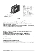
Figure 3 


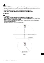
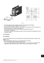
  Fit the anti-static bar with the emitters towards the material to be discharged.  

Use the supplied mounting materials, see fig. 1 and 3. 

  Mount the bar such that the emitters are at a distance of at least 50 mm from electrically con-

ductive machine parts. This prevents spark-over. 
If this distance cannot be achieved, an optional side panel can be placed,  
item number: 7510900010. 
Only use the side panel if absolutely necessary, as the bar operates less effectively when the 
side panel is fitted. 


4.4. Connection 
 
4.4.1. Earthing 


For personal protection and to ensure proper functioning, the following earth connections must 

both

 be made: 

  the fitted (yellow/green) earth wire to an earthed part of the machine. 

  the 0 V of the power cable on the supply side to earth. 

In the power units supplied by SIMCO (Nederland) B.V., the internal 0 V is connected to the 
safety earth. Make sure that the power cable of the power units is earthed correctly.  

Summary of Contents for Simco ThunderION

Page 1: ... Nederland B V Postbus 71 NL 7240 AB Lochem Telefoon 31 0 573 288333 Telefax 31 0 573 257319 E mail general simco ion nl Internet http www simco ion nl Traderegister Apeldoorn No 08046136 NL Gebruikershandleiding D Bedienungsanleitung GB User s Manual F Notice d utilisation 1 14 27 40 ...

Page 2: ...sluiten 7 4 4 1 Aarding 7 4 4 2 Voedingsspanning 8 4 4 3 Externe Bar operating OK signalering 8 5 Ingebruikneming 9 6 Controle op de werking 10 6 1 Intern 10 6 1 1 On LED 10 6 1 2 Fault LED 10 6 2 Weergave stand pulsfrequentie schakelaar met Fault LED en On LED 10 6 3 Extern Bar operating OK functie 10 6 4 Neutraliseren 11 7 Onderhoud 11 8 Storingen 12 9 Reparatie 12 10 Afdanken 12 11 Reserveonder...

Page 3: ...en in gebruik neemt Instructies in deze handleiding dienen te worden opgevolgd om een goede werking van het product te waarborgen en om aanspraak te kunnen maken op garantie Daar waar in deze handleiding wordt gesproken over staaf wordt steeds bedoeld ThunderION De garantiebepalingen zijn omschreven in de Algemene Verkoopvoorwaarden van SIMCO Nederland B V ...

Page 4: ...ker te verwijderen waardoor de staaf makkelijker en beter is te reinigen 2 Veiligheid Werkzaamheden aan de apparatuur door een elektrotechnisch vakbekwaam persoon laten uitvoeren Maak de apparatuur spanningsloos bij werkzaamheden aan de apparatuur Zorg voor een goede aarding van de apparatuur zie installatie Aarding is nodig voor een veilige en goede werking De onder hoogspanning staande emitters ...

Page 5: ...al Frequentie instelling 1 10 Hz in 1 Hz stappen instelbaar met de draaischakelaar achter de PG 7 blindstop Standaard 5 Hz stand 4 Weergave Pulsfrequentie instelling Knipperen rode en gele LED tijdens opstarten van de staaf en na het veranderen van de pulsfrequentie On signalering Gele LED Fault signalering Rode LED licht op bij overbelasting of kortsluiting Rode LED knippert wanneer er herhaaldel...

Page 6: ... AC naar 24 V DC voeding voor 1 ThunderION 4510001400 Control module voor max 4 ThunderION s Let op ThunderION s in combinatie met de control module zijn niet conform UL 7519020425 100 240 V AC naar 24 V DC DIN rail voeding voor 2 ThunderION s Let op ThunderION s in combinatie met deze voeding zijn niet conform UL 7519020430 100 240 V AC naar 24 V DC DIN rail voeding voor 2 ThunderION s Maximum to...

Page 7: ...Bij werkzaamheden aan de apparatuur maak de apparatuur spanningsloos Werkzaamheden aan de apparatuur door een elektrotechnisch vakbekwaam persoon laten uitvoeren Aarding is nodig voor een goede en veilige werking Gebruik uitsluitend de gespecificeerde spanningen op de circuits Gebruik uitsluitend meegeleverde bevestigingsmaterialen 4 3 Montage Let op Monteer de aansluitkabel zodanig dat deze mecha...

Page 8: ...plaatst worden artikel nummer 7510900010 Gebruik het zijschot alleen indien strikt noodzakelijk omdat de werking van de staaf minder effectief is als het zijschot wordt toegepast 4 4 Aansluiten 4 4 1 Aarding Voor persoonlijke veiligheid en een goede werking moeten de volgende aardverbindingen allebei gemaakt worden de gemonteerde geel groene aardedraad aan een geaard deel van de machine de 0 V van...

Page 9: ...it de voedingsspanning aan op pin 1 24 V en pin 6 0 V Pin 1 en 2 24 V Sluit de stuurspanning aan op Pin 2 24 V DC en Pin 5 0 V Pin 5 en 6 0 V Voor bedrading met een lengte tussen 20 en 40 m AWG20 Zie bijlage 2 4 4 3 Externe Bar operating OK signalering Het is mogelijk om de werking van de staaf op afstand te controleren met bijvoorbeeld een PLC Voor dit doel is er een optocoupler uitgang op de con...

Page 10: ...kelaar weer vervolgens knippert de Fault LED 10 keer snel daarna licht de On LED op De gele On LED licht even op daarna zal de rode Fault LED 10 keer snel knipperen daarna knippert de gele On LED langzaam een aantal keer dit geeft de stand van de pulsfrequentie schakelaar weer vervolgens knippert de Fault LED 10 keer snel daarna licht de On LED op Inschakelen Breng de stuurspanning aan op de remot...

Page 11: ...n uit te schakelen 6 2 Weergave stand pulsfrequentie schakelaar met Fault LED en On LED Na het inschakelen van de 24 V DC voedingsspanning wordt door middel van de Fault LED en On LED de stand van de pulsfrequentie schakelaar weergegeven Dit gaat als volgt te werk de rode Fault LED knippert 10 keer snel de gele On LED knippert langzaam Het aantal keer knipperen komt overeen met de stand van de sch...

Page 12: ... verwijderd worden tijdens het nat reinigen van de staaf Houd de ionisatiestaaf schoon Bij vervuiling reinig de ionisatiestaaf met een blokkwast en isopropyl alcohol Blaas de ionisatiestaaf volledig droog voor het in gebruik nemen Bij hardnekkige vervuiling kan ook Veconova 10 gebruikt worden www eco nova nl Bij reiniging niet alleen het montagevlak van de emitters reinigen maar ook de rest van de...

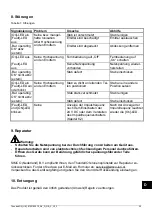
Page 13: ...rating OK niet actief Staaf sterk vervuild Staaf reinigen extern Staaf defect Staaf opsturen Fault LED en On LED knipperen aan en uit Geen Signalering van de pulsfre quentie na het inschakelen van de 24 V DC of het ver zetten van de pulsfrequen tieschaklaar Hoofdstuk 6 2 Na de weergave van de pulsfrequentie gaat On LED weer aan 9 Reparatie Waarschuwing Bij werkzaamheden aan de apparatuur apparatuu...

Page 14: ...rijving 1 7510990000 Emitter ThunderION schroefverbinding 1a 7510990020 Emitter ThunderION klikverbinding 2 7510900157 Montage beugel 3a 6603060120 6 polige connector 3b 7510004600 6 polige connector met snoer 6m 3c 7510004602 6 polige connector met snoer 12m 4 7510900010 Zijschot ThunderION ...

Page 15: ...n 20 4 4 1 Erdung 20 4 4 2 Speisespannung 20 4 4 3 Externe Signalisierung Bar operating OK 21 5 Inbetriebnahme 22 6 Funktionsprüfung 23 6 1 Intern 23 6 1 1 On LED 23 6 1 2 Fault LED 23 6 2 Anzeige der Stellung des Impulsfrequenzschalters mit Fault LED und On LED 23 6 3 Extern Funktion Bar operating OK 23 6 4 Neutralisieren 24 7 Wartung 24 8 Störungen 25 9 Reparatur 25 10 Entsorgung 25 11 Ersatztei...

Page 16: ...uktes vollständig durch Befolgen Sie die Anweisungen in dieser Anleitung um eine richtige Funktionsweise des Produktes sicherzustellen und Garantieansprüche geltend machen zu können Wenn in dieser Anleitung von einem Stab die Rede ist ist damit immer ThunderION gemeint Die Garantiebedingungen sind in den Allgemeinen Verkaufsbedingungen von SIMCO Nederland B V festgelegt ...

Page 17: ...er Stab lässt sich dadurch einfacher reinigen 2 Sicherheit Arbeiten am Gerät sind von elektrotechnisch fachkundigem Personal durchzuführen Schalten Sie die Netzspannung bei der Durchführung von Arbeiten am Gerät aus Sorgen Sie für eine richtige Geräte Erdung siehe Installation Erdung ist für eine sichere und einwandfreie Funktionsweise erforderlich Für die unter Hochspannung stehenden Emitter best...

Page 18: ...topfen Standard 5 Hz Stellung 4 Anzeige der Impuls frequenzeinstellung Blinken der roten und gelben LED beim Starten des Stabs und nach dem Ändern der Impulsfrequenz On Signalisierung Gelbe LED Fault Signalisierung Rote LED leuchtet bei Überlastung oder Kurzschluss auf Rote LED blinkt wenn Überlastungen oder Kurzschlüsse wiederholt oder ununterbrochen aufgetreten sind Fernbedienungs Funktionen Rem...

Page 19: ...chiene 100 240 V AC auf 24 V DC für 2 ThunderION Systeme Achten Sie auf Folgendes ThunderION Systeme sind in Kombination mit dieser Stromversorgung nicht UL konform 7519020435 Stromversorgung auf DIN Schiene 100 240 V AC auf 24 V DC für 6 ThunderION Systeme Achten Sie auf Folgendes ThunderION Systeme sind in Kombination mit dieser Stromversorgung nicht UL konform Für weitere Informationen zu diese...

Page 20: ...en Kreisen nur die angegebenen Spannungen an Verwenden Sie ausschließlich die mitgelieferten Befestigungsmittel 4 3 Montage Achtung Verwenden Sie ausschließlich die mitgelieferten Befestigungsmittel Leitende Maschinenteile in der Nähe des Ionensprühstabs haben einen nachteiligen Einfluss auf den Neutralisierungseffekt Um ein optimales Ergebnis zu erzielen muss der Ionensprühstab wie in Abbildung 1...

Page 21: ...ie Wirkung des Stabs bei Montage der Seitenwand weniger effizient ist 4 4 Anschließen 4 4 1 Erdung Zur Sicherheit von Personen und für eine gute Funktionsweise sind beide nachfolgenden Erdverbindungen herzustellen der montierte gelb grüne Erdungsleiter an einen geerdeten Teil der Maschine der 0V Anschluß des Netzteilkabels an der Netzteilseite mit der Erde verbinden Bei den von SIMCO Nederland B V...

Page 22: ...eßen an Pin 2 24 V DC und Pin 5 0 V Pin 5 und 6 0 V Zur Verkabelung bis zu einer Länge von 20 bis 40 m AWG20 Siehe Anhang 2 4 4 3 Externe Signalisierung Bar operating OK Sie können die Funktionsweise des Stabs aus der Entfernung kontrollieren z B mit einer SPS Für diesen Zweck ist ein Optokopplerausgang am Steckverbinder vorhanden max Belastung 30 V DC 50 mA Schließen Sie die externe Signalisierun...

Page 23: ...uenzschalters an dann blinkt die Fault LED 10 Mal schnell anschließend leuchtet die On LED Die gelbe On LED leuchtet kurz auf danach blinkt die rote Fault LED 10 Mal schnell dann blinkt die gelbe On LED mehrmals langsam dies zeigt die Stellung des Impulsfrequenzschalters an dann blinkt die Fault LED 10 Mal schnell anschließend leuchtet die On LED Einschalten Bringen Sie an den Kontakten der Ein Au...

Page 24: ...versorgung mehrere Sekunden lang ausgeschaltet wird 6 2 Anzeige der Stellung des Impulsfrequenzschalters mit Fault LED und On LED Nach dem Einschalten der 24 V DC Netzspannung wird mithilfe der Fault LED und On LED die Stellung des Impulsfrequenzschalters angezeigt Dies funktioniert wie folgt Die rote Fault LED blinkt 10 Mal schnell Die gelbe On LED blinkt langsam Die Anzahl Blinkvorgänge entspric...

Page 25: ...ab sauber Bei Verschmutzung Reinigen Sie den Ionensprühstab mit einer harten Nichtmetall Bürste Reinigen Sie den Ionensprühstab bei Verschmutzung mit einem Flächenstreicher und Isopropylalkohol Blasen Sie den Ionensprühstab vollständig trocken bevor Sie ihn in Gebrauch nehmen Bei hartnäckigen Verschmutzungen kann auch Veconova 10 als Reinigungsmittel verwendet werden www eco nova de Reinigen Sie n...

Page 26: ...dere Position setzen Bar operating OK nicht aktiv Stab stark verschmutzt Stab reinigen extern Stab defect Stab einschicken Fault LED und ON LED blinken Keine Anzeige der Impulsfrequenz nach dem Einschalten der 24 V DC oder dem Verstellen des Impulsfrequenzschalters Kapitel 6 2 Nach der Anzeige der Impulsfrequenz leuchtet wieder die On LED 9 Reparatur Warnung Schalten Sie die Netzspannung bei der D...

Page 27: ...ng 1 7510990000 Emitter ThunderION Schraubverbindung 1a 7510990020 Emitter ThunderION Klickverbindung 2 7510900157 Montagebügel 3a 6603060120 6 poliger Stecker 3b 7510004600 6 poliger Stecker mit kabel 6 m 3c 7510004602 6 poliger Stecker mit kabel 12 m 4 7510900010 Seitenwand ThunderION ...

Page 28: ...ection 33 4 4 1 Earthing 33 4 4 2 Supply voltage 34 4 4 3 External Bar operating OK signaling 34 5 Commissioning 35 6 Functional check 36 6 1 Internal 36 6 1 1 On LED 36 6 1 2 Fault LED 36 6 2 Indication of pulse frequency switch position with Fault LED and ON LED 36 6 3 External Bar operating OK function 36 6 4 Neutralizing 37 7 Maintenance 37 8 Faults 38 9 Repair 38 10 Disposal 38 11 Spare parts...

Page 29: ...ion the product Follow the instructions set out in this manual to ensure proper operation of the product and to retain your entitlement under the guarantee Where the word bar is used in this manual it refers in all cases to the ThunderION The terms of the guarantee are set out in the SIMCO Nederland B V General Terms and Conditions of Sale ...

Page 30: ...An emitter with a click connection is easier to remove making it easier and more convenient to clean the bar 2 Safety Work on the equipment must be carried out by a skilled and qualified electrical engineer When working on the equipment always disconnect the power supply to the equipment Make sure that the equipment is properly earthed see installation Earthing is needed to ensure safe and proper ...

Page 31: ... after adjustment of the pulse frequency On signalling Yellow LED Fault signalling Red LED lights up in the case of an overload or short circuit Red LED flashes when a repeated or continuous overload or short circuit has occurred Remote functions Remote On Off Switching high voltage on and off Control voltage specifications 10 V DC 10 mA min 30 V DC 25 mA max Bar operating OK Indicates that the ba...

Page 32: ...to UL standards For more information on these power supplies please contact SIMCO Nederland B V or your regional agent 4 Installation 4 1 Prior check Check that the bar is undamaged and that you have received the correct model Check that the data on the packing slip corresponds to the data shown on the received product If you have any problems and or if in doubt please contact SIMCO Nederland B V ...

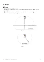
Page 33: ...ote Use only the supplied fasteners Conductive machine parts in the vicinity of the anti static bar stop it from working properly For optimum results the anti static bar must be fitted as shown in Figure 1 For minimum distances see Figure 2 Figure 1 Figure 2 ...

Page 34: ...el can be placed item number 7510900010 Only use the side panel if absolutely necessary as the bar operates less effectively when the side panel is fitted 4 4 Connection 4 4 1 Earthing For personal protection and to ensure proper functioning the following earth connections must both be made the fitted yellow green earth wire to an earthed part of the machine the 0 V of the power cable on the suppl...

Page 35: ... here Connect the supply voltage to pin 1 24 V and pin 6 0 V Pins 1 and 2 24 V Connect the control voltage to Pin 2 24 V DC and pin 5 0 V Pins 5 and 6 0 V For wiring with a length between 20 and 40 m AWG20 See appendix 2 4 4 3 External Bar operating OK signaling It is possible to check the bar s functioning remotely with a PLC for instance For this purpose an optocoupler output is available on the...

Page 36: ...ncy switch the Fault LED flashes 10 times quickly and then the On LED lights up The yellow On LED lights up briefly the red Fault LED will then flash 10 times quickly the yellow On LED then flashes a number of times slowly this indicates the position of the pulse frequency switch the Fault LED flashes 10 times quickly and then the On LED lights up Switching on Connect the control voltage to the re...

Page 37: ...2 Indication of pulse frequency switch position with Fault LED and ON LED After the 24 V DC supply voltage is switched on the Fault LED and On LED are used to indicate the position of the pulse frequency switch This works as follows the red Fault LED flashes 10 times quickly the yellow On LED flashes slowly The number of flashes corresponds to the position of the switch 0 to 9 flashes the red Faul...

Page 38: ...not be removed when wet cleaning the bar Keep the anti static bar clean If fouled clean the anti static bar with a hard non metal brush If fouled clean the anti static bar with a block brush and isopropyl alcohol Blow the anti static bar completely dry before use Veconova 10 may also be used in the event of stubborn fouling www eco nova nl During cleaning clean the mounting surface of the emitters...

Page 39: ...lean bar external Bar faulty Return bar Fault LED and ON LED flash on and off None Signalling of the pulse fre quency after the 24 V DC has been switched on or the pulse frequency switch has been turned Section 6 2 After the pulse frequen cy has been displayed the On LED turns on again 9 Repair Warning When working on the equipment always disconnect the power supply to the equipment Repairs must b...

Page 40: ...n 1 7510990000 Emitter ThunderION screw connection 1a 7510990020 Emitter ThunderION click connection 2 7510900157 Mounting bracket 3a 6603060120 6 pole connector 3b 7510004600 6 pole connector with cable 6 m 3c 7510004602 6 pole connector with cable 12 m 4 7510900010 ThunderION side panel ...

Page 41: ...nsion d alimentation 46 4 4 3 Indicateur externe de fonctionnement normal de la barre 47 5 Mise en service 48 6 Vérification du fonctionnement 49 6 1 Interne 49 6 1 1 Voyant de fonctionnement 49 6 1 2 Voyant de défaillance 49 6 2 Position de réglage de l interrupteur de fréquence d impulsion voyant Fault et voyant On 49 6 3 Externe fonctionnement de la barre 49 6 4 Neutralisation 50 7 Entretien 50...

Page 42: ...taller et de mettre en service le produit Il est important de respecter les instructions afin d assurer le bon fonctionnement du produit et de donner droit à sa garantie Dans cette notice le terme barre désigne systématiquement la barre ThunderION Les termes de la garantie sont mentionnés dans les conditions générales de vente de SIMCO Nederland B V ...

Page 43: ...déclic est plus facile à enlever car la barre se nettoie mieux et plus facilement 2 Sécurité Le travail sur l équipement doit être réalisé par un électricien compétent et qualifié Lorsque vous travaillez sur l équipement déconnectez toujours l alimentation de l équipement Assurez vous que l équipement est correctement relié à la terre voir la section Installation La mise à la terre est nécessaire ...

Page 44: ...nce d impulsion Les voyants rouge et jaune clignotent au démarrage de la barre et après le changement de la fréquence d impulsion Indicateur de fonctionnement Voyant jaune Indicateur de défaillance Le voyant rouge s allume en cas de surcharge ou de court circuit Le voyant rouge clignote lorsqu une surcharge ou un court circuit survient fréquemment ou en continu Fonctions à distance Mise sous tensi...

Page 45: ...DIN 100 240 V CA à 24 V CC pour 2 ThunderION Attention Les ThunderION utilisés en combinaison avec cette alimentation ne sont pas conformes UL 7519020435 Alimentation par rail DIN 100 240 V CA à 24 V CC pour 6 ThunderION Attention Les ThunderION utilisés en combinaison avec cette alimentation ne sont pas conformes UL Pour plus d informations sur ces alimentations contactez SIMCO Nederland B V ou v...

Page 46: ...onnement correct et sans risque Reliez uniquement les tensions spécifiées aux circuits Utilisez exclusivement les éléments de fixation fournis 4 3 Montage Attention Utilisez uniquement les attaches fournies La présence d éléments conducteurs de machine à proximité de la barre ionisante entrave le fonctionnement de cette dernière Pour un résultat optimal la barre ionisante doit être montée en suiva...

Page 47: ...e 4 4 Branchement 4 4 1 Mise à la terre Pour assurer la protection des personnes et un bon fonctionnement de l équipement les deux connexions à la terre suivantes doivent être établies reliez le câble de mise à la terre fourni jaune vert à une pièce mise à la terre de la machine reliez la broche 0 V du câble d alimentation sur le côté de l alimentation à la terre Dans les blocs d alimentation four...

Page 48: ...de commande à la broche 2 24 V CC et 5 0 V aux broches 5 et 6 0 V Pour un circuit d une longueur comprise entre 20 et 40 m AWG20 Voir annexe 2 4 4 3 Indicateur externe de fonctionnement normal de la barre Il est possible de vérifier le fonctionnement de la barre à distance par exemple à l aide d un CPL Pour cela une sortie de photocoupleur est disponible sur le connecteur charge max 30 V CC 50 mA ...

Page 49: ...osition de l interrupteur de fréquence d impulsion Ensuite le voyant Fault clignote 10 fois puis le voyant On s allume Le voyant jaune On s allume un instant puis le voyant rouge Fault clignote 10 fois Ensuite le voyant jaune On clignote lentement plusieurs fois il indique à nouveau la position de l interrupteur de fréquence d impulsion Ensuite le voyant Fault clignote 10 fois puis le voyant On s ...

Page 50: ...nt On Après la mise en circuit de l alimentation 24 V DC la position de l interrupteur de fréquence d impulsion est indiquée par les voyants Fault et On Le fonctionnement est le suivant le voyant rouge Fault clignote 10 fois rapidement le voyant jaune On clignote lentement Le nombre de clignotements correspond à la position de l interrupteur 0 t m 9 clignotements le voyant rouge Fault clignote 10 ...

Page 51: ...rre Gardez la barre antistatique propre Si la barre est sale nettoyez la à l aide d une brosse dure non métallique En cas d encrassement nettoyez les barres ionisantes avec une brosse et un peu d alcool isopropylique Séchez les barres ionisantes complètement avant de les utiliser En cas d encrassement persistant vous pouvez aussi utiliser du Veconova 10 www eco nova nl En cas de nettoyage il ne su...

Page 52: ... sur les émetteurs La barre est trop près des pièces conductrices Eloignez la barre Indicateur de fonc tionnement de la barre désactivé La barre est très sale Nettoyez la barre externe La barre est défaillante Renvoyez la barre Voyants Fault et ON clignotants Aucun Indication de la fréquence d impulsion après la mise en circuit de l alimentation 24 V DC ou la modifica tion de l interrupteur de fré...

Page 53: ...1 Pièces Pos Réf de pièce Description 1 7510990000 Emetteur de la barre ThunderION raccord à vis 1a 7510990020 Émetteur ThunderION raccord par déclic 2 7510900157 Support de montage 3a 6603060120 Connecteur 6 pôles 3b 7510004600 Connecteur 6 pôles avec câble de 6 m 3c 7510004602 Connecteur 6 pôles avec câble de 12 m 4 7510900010 Panneau latéral pour barre ThunderION ...

Page 54: ...ThunderION_UM_9752160010_NL_D_GB_F_V2_2 53 Bijlage 1 Aansluitschema s Anhang 1 Anschlußschemas Appendix 1 Wiring diagrams Annexe 1 schémas de câblage ...

Page 55: ...ThunderION_UM_9752160010_NL_D_GB_F_V2_2 54 Bijlage 1 Aansluitschema s Anhang 1 Anschlußschemas Appendix 1 Wiring diagrams Annexe 1 schémas de câblage ...

Page 56: ...ThunderION_UM_9752160010_NL_D_GB_F_V2_2 55 Bijlage 2 Aansluitschema Anhang 2 Anschlußschema Appendix 2 Wiring diagram Annexe 2 schéma de câblage ...

Reviews: