background image

1.  A leaking battery can result in poor performance, and could potentially damage the unit.  We recommend

inspecting the battery periodically, even if the

 indicator is not showing on the display,

to make sure the battery is intact.

2.  As mentioned previously, we also recommend replacing the battery at least once a year, even if the

  indicator is not showing on the display.  If the unit is frequently activated during main power

outages, requiring it to dial phones while running on battery power, you may wish to replace the battery
more frequently.

3.  Avoid mounting the autodialer unit in areas that are exposed to environmental extremes such as high heat.

humidity, or high levels of airborne dust or chemical vapors, as this could damage the unit or cause it to
perform unreliably.

4.  If it is necessary to clean the unit, use only a damp cloth and mild household cleaning agents.  Do not spray

cleaning fluids directly onto the unit itself; instead, spray the cleaner onto the cloth and wipe the unit clean.
Under no circumstances should the unit be cleaned with strong solvents such as turpentine, paint thinner,
gasoline, etc.

  Care and maintenance of your APD-T01 Telephone Autodialer:

Distributed In North America by:

Interworld Electronics & Computer Industries Inc.

145 Tyee Drive, Point Roberts, WA 98281

Tel: 1-425-223-4311 Toll Free: 1-877-902-2979

sales@interworldna.com http://www.interworldna.com

In Canada Call: 1-604-925-6150 or Toll Free 1-800-663-6001

sales@interworld.ca http://www.interworldna.com.

Summary of Contents for APD-T01

Page 1: ...APD T01 Telephone Auto Dialer installation user guide ...

Page 2: ... answers until one of them acknowledges the message by pressing the or key on their phone The unit can even be programmed to play one of two different messages depending on which trigger input is activated and to only call certain numbers for one trigger vs another It also has a built in audible alarm and is able to dial out even while running on battery power Note that the APD T01 is designed to ...

Page 3: ...er is just a dry contact relay signal the trigger signal is essentially immune to interference from induced EM or RF noise so the wiring between the autodialer and the monitoring unit can be dozens or even hundreds of feet if necessary Just make sure the wiring is routed such that no one can trip over it and that it can t get crushed or damaged by equipment rolling over it When choosing a spot for...

Page 4: ...riction lock so be careful when removing or replacing the cover For now go ahead and remove the cover and set both it and the screw aside but do not install the 9V battery just yet In addition to the 9V battery connector you will find a small switch marked Normal Erase Make sure this switch is in the Normal position The first thing to do is hook up the trigger and anti tampering signals from the A...

Page 5: ...sh If not you should jumper the two TAMP terminals together with a short piece of wire as shown below IMPORTANT NOTE if this anti tamper function is not going to be used the TAMP terminals should be jumpered together with a short piece of wire as shown here Connecting the anti tamper switch signal security alarm panel TAMP TR2TR1 0V 12V if the anti tamper function is desired run a 2 conductor pair...

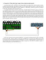
Page 6: ...s should be usually be connected to the NO Normally Open contact pairs of the monitoring unit s relays Example 1 One relay output one trigger input The simplest application of course is using a single trigger input in combination with a single output from a single monitoring unit in this example a RelayGoose II Note that since the relay outputs on an ITWatchDogs monitoring device are true dry cont...

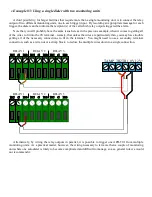
Page 7: ...e inserted into a single terminal so you will probably find it much easier to make this connection on the larger relay terminal block instead especially since the side of the DC power supply also has to be connected into the 0V terminal at the APD T01 side If the alarm wire pairs are thin enough though there s no reason not run two complete wire pairs between the APD T01 and the monitoring unit to...

Page 8: ... in the previous example when it comes to getting all of the wires to fit into the 0V terminal namely that unless the wires are particularly thin you may have trouble getting all of the necessary connections to fit in the terminal You might need to use a secondary terminal connection such as a wire nut or a crimp block to reduce the multiple wires down to a single connection Alternatively by wirin...

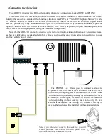
Page 9: ...f having the autodialer to begin with Note that the APD T01 can not be directly connected to most multi extension office phone intercom systems as they generally do not use standard telephone voltages and signaling conventions between the extension phones and the central control system The PHONE jack allows you to connect a standard telephone device to the line as well so that the line can be used...

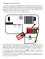
Page 10: ...st once a year even if the APD T01 is not displaying a Low Battery icon on its display to insure correct operation of the unit We would also recommend inspecting the battery every so often to make sure the battery isn t damaged or leaking if the battery doesn t look right discolored swollen leaking visible corrosion around the terminals etc or if the Low Battery icon shows on the display the batte...

Page 11: ...as an option check with ITWatchDogs sales department for more details The model included in the APD T01 kit comes with two bare wires at the end pre stripped and tinned for insertion into the screw terminals The proper connection is shown below unstriped wire is negative and goes to 0V terminal striped wire is positive and goes to 12V terminal IMPORTANT NOTE If the power supply which comes with yo...

Page 12: ... the APD T01 must be in the or inactive mode for any programming operations If this is your first time programming the unit it should come up by default if the LCD display shows instead key in the four digit password and press ESC to switch to mode In the following instructions whenever it is necessary to enter the four digit password we will indicate this as x x x x Out of the box the factory def...

Page 13: ...up and re type the number 5 Press ENTER to save the number then ESC to exit programming mode Repeat this process as needed until you have entered all of the numbers up to a maximum of 9 which you want to the autodialer to be able to call once it has been triggered Deleting already programmed phone numbers To erase a previously programmed phone number use the following sequence 1 Key in the four di...

Page 14: ...mming 5 Press a number from 1 to 9 to select which of the 9 phone number presets you wish to enable or disable for this trigger Each time you press a number it toggles that particular number on or off enabled numbers will display as a number while disabled ones will display as a dash 6 Once you have set the dialing list programmed the way you want it press ENTER to save the list Repeat this proces...

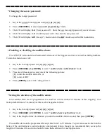
Page 15: ...sword x x x x 2 Press PROGRAM 2 ENTER to select audible alarm length setting mode 3 Key in the length of time in minutes you want the audible alarm to sound then press ENTER The audible alarm can be programmed for anywhere from 1 to 99 minutes To prevent excessive drain on the battery if the unit happens to activate during a main power failure though we recommend that you keep the length to 20 min...

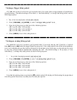
Page 16: ...0 to set the delay to 00 seconds 3 to set the delay to 30 seconds 6 to set the delay to 60 seconds 4 Press ENTER to save this setting and exit Note that if an arming delay is set then the symbol on the LCD display will flash during the programmed time delay period then come on solidly once the delay has expired Setting a Trigger Delay period The APD T01 can be set to wait for a given period of tim...

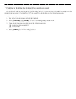
Page 17: ...und during the delay period The default is off no sound to change this use the following sequence 1 Key in the four digit password x x x x 2 Press PROGRAM 7 ENTER to select set arming delay sound mode 3 Press one of these keys to select one of the following options 0 to turn the delay sound OFF 1 to turn it ON 4 Press ENTER to save this setting and exit ...

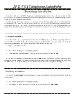
Page 18: ... programmed it needs to be turned or armed so that the trigger inputs become active and the unit is ready to dial Note that you must have programmed at least one message and one phone number into the autodialer or it will not do anything when the input is triggered Arming the autodialer is simple 1 Key in the four digit password x x x x 2 Press ENTER to arm the dialer The LCD display will change f...

Page 19: ...until all of the numbers on the dialing list have been called It will repeat this entire sequence three times until one of the called phone numbers responds if none of the numbers have responded after the third time through the list the autodialer will stop dialing and display on the LCD display During this sequence any of the called numbers can acknowledge the alarm and stop the dialing sequence ...

Page 20: ...wall 2 Open the 9V battery compartment and remove the 9V backup battery 3 Move the switch to the ERASE position 4 Reconnect the AC power supply but do not reconnect the battery The LCD display should show in large letters 5 Press the DELETE key twice the unit should acknowledge this with a double beep 6 Disconnect the AC power supply again then move the switch back to the NORMAL position 7 Replace...

Page 21: ...h heat humidity or high levels of airborne dust or chemical vapors as this could damage the unit or cause it to perform unreliably 4 If it is necessary to clean the unit use only a damp cloth and mild household cleaning agents Do not spray cleaning fluids directly onto the unit itself instead spray the cleaner onto the cloth and wipe the unit clean Under no circumstances should the unit be cleaned...

Reviews: