background image

www.metsjo.se

Ver. 2011-10

16

7

BPW trailer axle
with butterfly cam brakes

BPW trailer axle
with flat cam brakes

BPW trailing steering axle

BPW trailer axle
with wedge�type brake

English

6

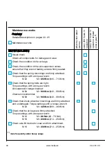
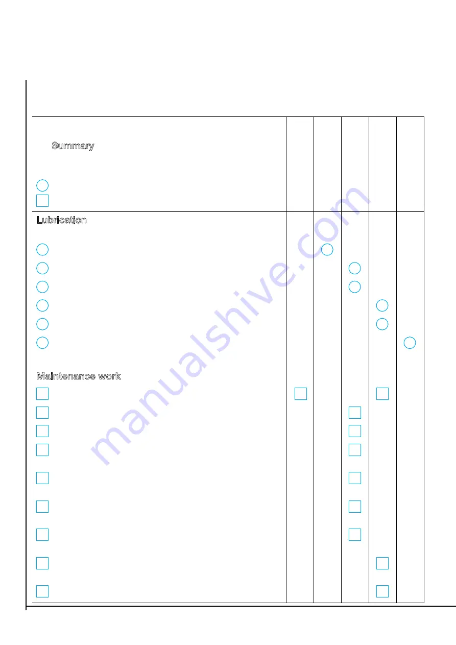
Lubrication and maintenance works

Summary

Detailed description on pages 8 � 18

Lubrication
Maintenance works

Lubrication

with BPW special longlife grease (ECO�Li 91)

1

Steering pivot bearings, top and bottom

2

Locking cylinder ends on steering axles

3

Outer and inner brake camshaft bearings

4

Slack adjuster

5

ECO�Master automatic slack adjuster

6

Change grease in wheel hub bearings,
check taper roller bearings for wear

Maintenance work

1

Check that wheel nuts are tight, retighten if necessary.

2

Check hubs for bearing play, adjust if necessary.

3

Check brake linings.

4

Check the brake adjustment on the brake lever, 
adjust if necessary.

5

Check the brake adjustment on the slack adjuster,
adjust if necessary.

6

Check brake adjustment on wedge�type brakes,
adjust if necessary.

7

Check brake adjustment on Backmat cam brakes, 
adjust if necessary.

8

Check brake adjustment on the automatic 
slack adjuster, adjust if necessary.

9

Check the operation of the automatic slack adjuster.

After the first laden jour

ney

Every 40 hours in operation

Every 200 hours in operation

Every 500 hours in operation (annually)

BPW trailer axles

Every 1000 hours in operation (annually)

Summary of Contents for 4300011

Page 1: ...Ver 2011 10 www metsjo se 1 MetaMid Instructions and maintenance ...

Page 2: ...e trailer the future settings and adjustments will be made For you ease and to avoid future mistakes in connection with maintenance and spare parts questions we advise you to write down the type of the trailer its serial number and manufacturing year This information you can find on the manufactures plate which is placed on the long left side of chassis frame Serial number Trailer Manufacturing ye...

Page 3: ... mm Manual telescopic support leg Hydraulic brakes 2 pieces per axle 45 according to VVFS 2003 6 Manually adjusted brakes Cover sheets stop dirt entering brake drum Back tipping tipping angle 55º Oil volume 10L 210bar Electrical system 12 Volts Rear ball coupler for the containers dia 76mm distance between them 1100mm Prepared consoles for mounting an axle lifting system Rear drawbar type clevis r...

Page 4: ...er 3 Check if the tailgate is opened hydraulic mechanical tailgate 4 Tipping should take place on a flat and solid surface 5 Secure area while tipping 15 metres in radius 6 The tractor must always be connected to the trailer during tipping 7 Never drive with a container which is up tipped 8 S 9 The system is NOT equipped with a chock valve Attention Lowering a loaded container while tipping can ca...

Page 5: ... 1 Pendulum bogie in the centre 1 1 fig 1 2 Tipping rear ball coupler 1 1 fig 2 3 Tipping cylinder 1 1 bearing fig 3 4 The axles according the manufactures maintenance document Attention While working under a container the ball valve that is on the tipping cylinder must always be closed Hydraulic system for 230 bars hydraulic pressure Fig 1 Greasing pendelboggi Fig 4 Greasing Art 10400127 Fig 2 Gr...

Page 6: ...t Metamid 0 00 11 1 101011 10400468 Tillverkarskylt Ivarsson i Metsjö NITBAR 0 04 12 2 101971 10250052 Reflex orange själv häft 60 mm 0 01 13 4 ISO 8676 M30x2 0 x 60 N 14 2 ISO 4162 M10 x 30 x 30 N 15 1 106638 bakljus konsoler 10 32 16 2 102742 416007 Kantskydd 15x12 6 8 PVC Svart 0 03 17 1 102743 416007 Kantskydd 15x12 6 8 PVC Svart 0 01 This document must not be copied without our written per mi...

Page 7: ...Av Titel Benämning Artikel Nr Skala Generell Tolerans Rev Blad E Hall Plats Vikt kg 617 59 40 10 10 200 10 10 564 10 10 11 13 7 14 4 17 16 This document must not be copied without our written per mission and the contents thereof must not be imparted to a third party nor be used for any unauthorized purpose Contravention will be prosecuted 8 7 6 5 4 3 2 1 F E D C B A F B E C A D 7 8 1 6 4 2 3 5 God...

Page 8: ...73 51x27L23 Nedre tippkolvshylsa No Mid MX 0 16 14 2 0160 0160Bock Tippstödsplåt 1 89 15 1 107835 Ramstyning Mid Mx spindelhhylsa Boggihylsa 175 11 16 1 100109 100x100x8L230 Borrad Stödbenshylsa 4 97 17 2 107904 Lock 100x100 22 t 5 18 1 0585 0585 Förstärkning drag MX 2 19 This document must not be copied without our written per mission and the contents thereof must not be imparted to a third party...

Page 9: ...attstål 30x10L170 14 7 107845 Rundstång 20 15 2 102741 HLB 8 2 kedjelänk 0 05 16 1 0248 0248 Boggiebocksbricka Mid MX 0 65 17 1 100486 10400126 5 Komplett dragögel Mid 9 76 18 1 107874 UNP 80 19 1 107885 Plåt drag Mid ramstyrn 20 2 107887 Plåt drag Mid ramstyrn 21 1 107888 Plåt drag Mid ramstyrn 22 2 107889 Plåt drag Mid ramstyrn 23 1 107906 Rundstång 20 F E B A D c 1 2 3 4 5 6 7 8 9 10 C B A D E ...

Page 10: ...100982 1223214010 Reflex 40x90mm gul 0 03 6 2 100958 30x3L170 Plastbit hållare till triangelreflex 0 02 7 2 100959 10250055 2 kabel bakljus 0 03 8 2 100961 58102016 Gummiklammer 16 mm 9 4 100962 B6FK FXB Borrskruv 3 5x16 10 4 ISO 1207 M5 x 16 16N 11 4 Hexagon Nut ISO 4032 M8 W N 12 4 Hexagon Flange Nut ISO 4161 M5 N 13 2 100954 10250047 Glödlampa baklyse 12V 10W 0 01 14 4 100954 10250046 Glödlampa...

Page 11: ...Ver 2011 10 www metsjo se 11 ...

Page 12: ...10 02 5220 75 82 VM 24x1 5 1 410120222 40B Plugg 10 02 3704 56 00 D20 7 2 410120223 43 Bromsnock 10 05 097 36 95 5 L 253 1 410120224 53 Bricka 10 03 311 50 13 0 42 34x4 1 410120225 54 Låsring 10 02 5603 29 90 29x1 5 1 410120226 59 Bromshävarm GSK 10 05 174 40 16 0 1 410120227 73 Bromsback kpl m belägg 10 05 091 15 21 0 2 410120228 79 Bromsbelägg 10 03 092 19 50 0 2 410120229 80 Nit 10 02 5805 61 0...

Page 13: ...0 02 5220 75 82 VM 24x1 5 1 410120222 40B Plugg 10 02 3704 56 00 D20 7 2 410120223 43 Bromsnock 10 05 097 36 95 5 L 253 1 410120224 53 Bricka 10 03 311 50 13 0 42 34x4 1 410120225 54 Låsring 10 02 5603 29 90 29x1 5 1 410120226 59 Bromshävarm GSK 10 05 174 40 16 0 1 410120227 73 Bromsback kpl m belägg 10 05 091 15 21 0 2 410120228 79 Bromsbelägg 10 03 092 19 50 0 2 410120229 80 Nit 10 02 5805 61 01...

Page 14: ...ke of the drawbar overrun hitch Model number model code Maximum load the difference between unladen weight and maximum laden weight kg 3 Technical data Axles and brakes Obtaining spare parts When spare parts are needed the model numbers and codes for the axles and chassis parts will greatly assist your BPW parts dealer or BPW service facility in quickly and accurately determin ing the appropriate ...

Page 15: ...rantee Maintenance work should be carried out at the prescribed intervals in order to maintain the safe operation of the vehicle The relevant operating and servicing instructions of the vehicle manufacturer and of the manufacturers of the other vehicle components must be observed All repair and maintenance work should only be carried out by a BPW approved Service Station unless the vehicle owner h...

Page 16: ... are tight retighten if necessary 2 Check hubs for bearing play adjust if necessary 3 Check brake linings 4 Check the brake adjustment on the brake lever adjust if necessary 5 Check the brake adjustment on the slack adjuster adjust if necessary 6 Check brake adjustment on wedge type brakes adjust if necessary 7 Check brake adjustment on Backmat cam brakes adjust if necessary 8 Check brake adjustme...

Page 17: ...Ver 2011 10 www metsjo se 17 7 BPW trailer axle with butterfly cam brakes BPW trailer axle with flat cam brakes BPW trailing steering axle BPW trailer axle with wedge type brake English ...

Page 18: ...ease nipples with BPW special longlife grease ECO Li 91 until clean grease emerges from the bearings While carrying out this lubrication ensure that the locking cylinder and the pipe contain no air at any time 3 Outer and inner brake camshaft bearings every 200 hours in operation and before use after a long period of inactivity Lubricate via the grease nipples with BPW special longlife grease BPW ...

Page 19: ...ed every 500 hours in operation at least once a year Remove the rubber cap Lubricate with BPW special longlife grease ECO Li 91 80 g until sufficient clean grease emerges from the adjusting bolt Undo the adjusting bolt by approximately one turn with a ring spanner Operate the brake lever by hand several times In doing so the automatic adjustment must operate smoothly Repeat several times if necess...

Page 20: ...ls thoroughly diesel oil and check to ensure that they are suitable for re use Lightly grease the bearing seats before fitting the bearings and then assemble all the parts in the reverse order Carefully drive the parts into place on the bearing shells without tilting or damaging them Coat the bearings the wheel hub cavity between the bearings and the bearing cap with grease before re assembly The ...

Page 21: ...006 GS 7008 50 g 210 g GS 8008 1 GS 8010 1 90 g 230 g GS 11008 1 GS 11010 1 170 g 290 g GS 12008 GS 12010 180 g 320 g Work grease into the space between the tapered rollers and the races Apply remainder to outer race of the hub The grease for the outer tapered roller bearing is pressed into the bearing as the hub cap filled with grease is screwed on English ...

Page 22: ...100 Nm M 14 x 1 5 22 5 125 Nm 120 130 Nm 125 Nm 120 130 Nm M 18 x 1 5 24 6 290 Nm 275 305 Nm 270 Nm 250 290 Nm 320 Nm 300 340 Nm M 20 x 1 5 27 8 380 Nm 360 400 Nm 380 Nm 360 400 Nm 420 Nm 400 440 Nm M 22 x 1 5 32 8 10 510 Nm 485 535 Nm 510 Nm 485 535 Nm 560 Nm 535 585 Nm M 22 x 2 32 10 460 Nm 435 485 Nm 505 Nm 480 530 Nm Torque settings for wheel nuts 2 Check the bearing play in the wheel hub ever...

Page 23: ...heel hub Whel hub bearing on BPW axles type GS 11008 1 GS 11010 1 GS 12008 GS 12010 1 Unscrew the hub cap 2 Remove the split pin from the castle nut 3 Tighten the axle nut using a torque wrench to 150 Nm while simultaneously turning the wheel hub Using a normal castle nut spanner vehicle tool kit tighten the castle nut until the wheel hub race is slightly braked 4 Turn back the castle nut to the n...

Page 24: ...rench at the same time as turning the wheel hub tightening torque 150 Nm If using a normal hook spanner 80 90 vehicle tool kit tighten the shaft nut until the running of the wheel hub is slightly braked 5 Turn the KMT shaft nut back by 15 30 6 Tighten 3 grub screws to a tightening torque of 18 Nm 7 Fill the hub neck with BPW special longlife grease ECO Li 91 The air connection must be free from gr...

Page 25: ... If using a normal hook spanner 80 90 vehicle tool kit tighten the shaft nut until the running of the wheel hub is slightly braked 4 Screw on the outer KM shaft nut by hand 5 Turn back the inner shaft nut 15 30 bend the locking plate projection into the groove in the shaft nut 6 Tighten the outer KM shaft nut to a tightening torque of 150 Nm Bend the locking plate projection into the groove in the...

Page 26: ... nuts remove the bolts Bend open the slot in the brake levers a little The brake levers can now be withdrawn Turn the brake camshafts until the linings start to rub against the brake drums Push the brake levers onto the brake camshafts in the correct position until they are fully home Insert the bolts and fit the nuts 3 Brake lining check every 200 hours in operation Open the inspection hole by re...

Page 27: ...osi tioning hole at least 50 mm into the hole Tighten the adjusting nuts item C on the wheel brakes with a spanner with the help of the adjusting bolt item B until the wheel will not turn in the direction of travel Turn back the adjusting bolt until no brak ing effect can be felt when the wheel is turned in a forward direction Caution The wheel brake must only be adjusted by means of the adjusting...

Page 28: ...ts are tight Torque settings with a torque wrench Air suspension hanger bracket M 30 M 900 Nm 840 990 Nm Channel crossmember M 30 M 900 Nm 840 990 Nm 5 Check that shock absorber mountings are firmly attached and undamaged Torque settings with a torque wrench M 24 M 420 Nm 390 460 Nm 6 Check that the air bags are firmly attached Torque settings with a torque wrench M 12 M 66 Nm 62 73 Nm M 16 M 230 ...

Page 29: ...Ver 2011 10 www metsjo se 29 21 BPW air suspension assembly BPW air suspension assembly with axle lift device English ...

Page 30: ...ke sure that the cylinder and the supply line are always vented Visual inspection every 200 hours in operation Check all components for damage and wear 1 Check the condition of the damping cylinders and check them for leaks every 500 hours in operation latest annually 2 Check damping cylinders attachment every 500 hours in operation at least once a year Check the damping cylinders are firmly attac...

Page 31: ...nitially after the first laden journey Check the bushes moving the vehicle slightly backwards and forwards with the brake applied or moving the spring eyes with a lever There must be no play in the spring eye If not attached properly the spring bolt may be damaged Check the lateral wear washers in the support Check that the M 30 lock nut on the spring bolts is tight Torque settings with a torque w...

Page 32: ... mobile storages Ivarsson s i Metsjö AB reserve the right to change technical specifications Data and illustrations are to be considered approximate and also include special accessories that are not part of the scope of standard supply Ivarssons i Metsjö AB 585 92 Linköping Phone office 46 13 593 10 Fax 46 13 590 84 www ivarssonsimetsjo se info ivarssonsimetsjo se ...

Reviews: