1-10
GENERAL SPECIFICATIONS
D
AILY
4
X
4
Base - May 2007
Print 603.93.761
Dimensions and masses
1.13.2
Determining the Centre of Gravity of the Body and Payload
Positioning on the longitudinal plane
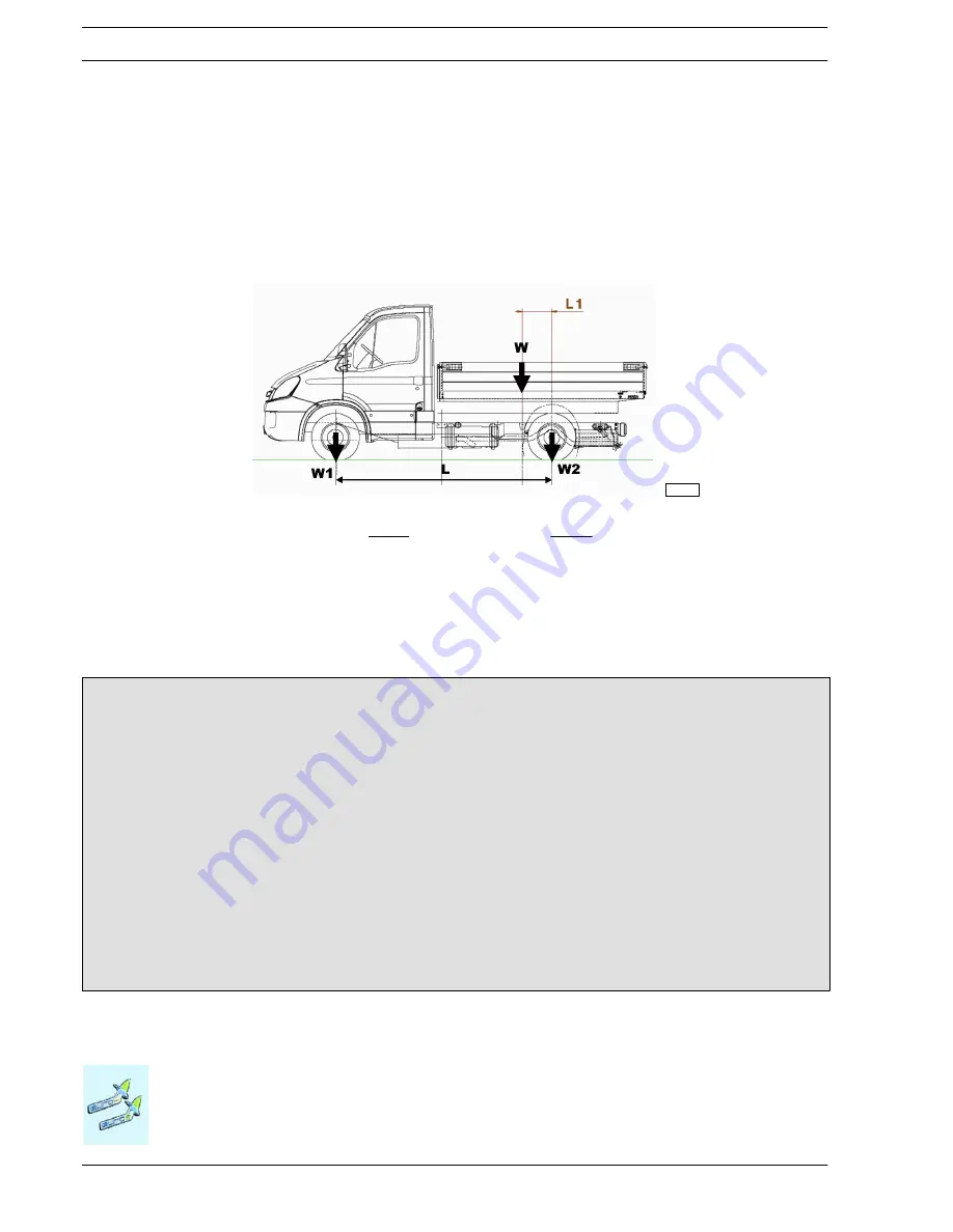
To establish the location of the centre of gravity of the body and payload the following examples below may be used as guidelines.
The technical documentation specific to each model (chassis cab drawing) give the positions permitted with the vehicle in its standard
form. The masses and positioning of the single components of the vehicle are given in the chassis and weight distribution diagram.
respectively
L1
=
L
−
W2
⋅
L
W
102452
Figure 1.1
W = Body + payload (kg)
W1 = Body and payload acting on front axle (kg)
W2 = Body and payload acting on rear axle (kg)
L1 = Distance of the centre of gravity from the rear axle centre line (mm)
L
= Wheelbase (mm)
L
1
=
W
1
⋅
L
W
Example of calculation of the load barycentre position
Consider a 40C13 vehicle with a wheelbase of 3450 mm with:
1. GWW= 4200 kg (permitted maximum: 1900 kg on the front and 3100 kg on the rear)
2. KERB WEIGHT = 1955 kg (1340 kg on the front axle, 615 kg on the rear)
The permitted maximum load (body + payload) will be W = 4200 - 1955 = 2245 kg. Let us calculate the position of the center
of gravity in which the maximum permitted on the front axle is achieved. Let us assume an uniform distributed load .
In this case, out of 2245 kg. W
1
= 1900 - 1340 = 560 kg will affect the front axle, while the remaining W
2
= 2245 - 560 = 1685
kg will affect the rear axle.
Thus, the following will be obtained:
1. W
1
= 560 kg
2. L
= 3450 mm
3. W = 2245 kg
L
1
= W
1
x L / W = 860 mm
The center of gravity of the load (Body + payload) must not be more than 860 mm far from the rear axle; otherwise, the front
axle would be overloaded.
Summary of Contents for DAILY 4x4
Page 1: ...DAILY VEHICLE 4X4 RANGE BODYBUILDER INSTRUCTIONS L I G H T R A N G E ISSUE 2007 ...
Page 4: ...Base May 2007 Print 603 93 761 Update data ...
Page 8: ...Base May 2007 Print 603 93 761 Index of section ...
Page 10: ...1 2 GENERAL SPECIFICATIONS DAILY 4X4 Base May 2007 Print 603 93 761 Index ...
Page 28: ...2 4 CHASSIS MODIFICATIONS DAILY 4x4 Base May 2007 Print 603 93 761 Index ...
Page 110: ...2 86 CHASSIS MODIFICATIONS DAILY 4x4 Base May 2007 Print 603 93 761 Chocks ...


