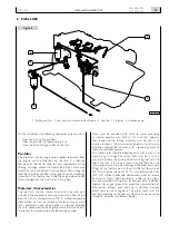
background image

NEF

N45 MNA M10

N67 MNA M15

4 - 6 cylinders in line 

diesel cycle

FOr MArine APPlicATiOns

INSTALLATION DIRECTIVE

MAy 2006 ediTiOn

T

e

c

H

n

O

l

O

G

i

c

A

l


e

X

c

e

l

l

e

n

c

e

Summary of Contents for N45 MNA M10

Page 1: ...NEF N45 MNA M10 N67 MNA M15 4 6 cylinders in line DIESEL CYCLE FOR MARINE APPLICATIONS INSTALLATION DIRECTIVE MAY 2006 EDITION T EC H N O L O G IC A L E X CELLENCE ...

Page 2: ...nce reliability and working life Exclusive use of IVECO Original Parts is a necessary condi tion to maintain the engine in its original integrity Tampering making modifications and using non original parts can jeopardize the safety of boat engineers and users To obtain spare parts you must indicate Commercial code serial number and indications shown on the engine tag Part number of the spare as pe...

Page 3: ...15 00 SECONDARY ANALOG INSTRUMENT PANEL fLyING BRIDGE 28 11 M10 00 M15 00 DRILLING PLANS FOR ANALOG PANELS 29 12 M10 00 M15 00 CUSTOMIZED INSTRUMENT PANEL 30 13 M10 00 M15 00 WIRING DIAGRAMS 32 N45 MNA M10 01 N67 MNA M15 01 39 14 M10 01 M15 01 INSTALLATION OVERVIEW 40 15 M10 01 M15 01 ELECTRICAL EQUIPMENT 41 16 M10 01 M15 01 MAIN ANALOG INSTRUMENT PANEL 46 17 M10 01 M15 01 SECONDARY ANALOG INSTRUM...

Page 4: ... COMMON CHAPTERS 63 21 SENSORS FOR DETECTION AND PANEL SIGNALING 64 22 PREPARING THE ENGINE FOR FIRST START UP 67 23 TESTS BEFORE THE FIRST START UP 67 24 FIRST ENGINE START 68 25 UNDERWAY CHECKS 68 26 PREPARING THE ENGINE FOR LONG IDLE PERIODS 69 27 APPENDIX 71 ...

Page 5: ...e to the electric system and to the fuel supply circuit and a new model identified with the code N45 MNA M10 01 or N67 MNA M15 01 was created detail B in figure 2 This document concerns both the models The relating contents are developed in different chapters which can be identified thanks to the presence in each title of the extension M10 00 M15 00 or M10 01 M15 01 Chapters 21 to the end of the d...

Page 6: ...uipment o Do not place voltage across the boat s on board electri cal system without first verifying that there are no short circuits o Do not branch pipes off to draw fuel from the engine supply lines o Do not make any change to the engine s hydraulic circuits and components o Do not execute arc welding operations before removing the electronic units from their seating placing them at an adequate...

Page 7: ...INSTALLATION DIRECTIVE MAY 2006 N45 MNA M10 N67 MNA M15 Long engine inactivity periods Before long periods of inactivity ready the engine following the procedure set out in Chapter 26 ...

Page 8: ...4 Location of sacrificial anode 5 Cooled exhaust manifold 6 Exhaust gas and sea water discharge pipeline 7 Lifting eyebolt 8 Rocker arm covers 9 Oil refill cap 10 Location of thermostatic valve 11 Cap for engine coolant outlet to sanitary water heating system 12 Coolant refill cap 13 Engine coolant tank 14 Auxiliary belt automatic tensioner 15 Alternator 16 Cap for engine coolant discharge and rec...

Page 9: ...A M10 00 and N67 MNA M15 00 7 Low pressure mechanical feed pump 8 Fuel intake fitting 9 Fuel filter 10 Combustion air filter 11 Lifting eyebolt 12 Oil vapours vent 13 Oil dipstick 14 Lifting eyebolt 15 Sea water junction pipe from after cooler to engine coolant sea water heat exchanger Oil gearbox heat exchanger on request 16 Connector for instrument panel connection wire harness N45 MNA M10 01 an...

Page 10: ...with sea water mm inches 127 5 5 Fuel supply Transfer pump delivery at maximum rpm l h 140 Flow rate return to tank l h 120 Fuel temperature C 60 Inner diameter intake pipe mm 8 Inner diameter return pipe mm 8 Thread on pre filter junctions M 14 x 1 5 Free height below filter to replace filter mm 30 Allowed intake vacuum kPa mmH2 O 15 1500 Allowed on tank return pipe back pressure kPa mmH2 O 10 10...

Page 11: ...ion N 1340 For direction of the resulting radial force between 60 and 300 with reference to the cylinder axis piston at top dead center 0 2 race front pulley elastic joint Torque available in engine axis Nm 150 15 Moment of inertia of rigidly added masses kgm2 0 015 04_428_N 588 5 799 31 45 60 2 36 915 36 02 390 15 35 390 15 35 358 14 09 342 13 46 30 1 18 355 13 97 355 13 97 257 10 12 04_403_N 828...

Page 12: ...the pump it is best to interpose a gate to be closed in emergencies or for extended idle periods and a filter to stop the smaller impurities it is also recommended to install a suitably dimensioned and easily replaced zinc anode The engine sea water line was provided by the manufacturer with protection anodes to be replaced periodically The rubber hoses positioned along the pipeline shall be suffi...

Page 13: ... the accumulation of electrostatic charges Tanks must be provided with vents to avoid exceeding an internal pressure of 5kPa 0 5 m of H2 O column their shape and the suction assembly must be such as to assure a suction at the maximum longitudinal and transverse inclination allowed for the boat with a residual quantity of fuel oil considered reserve The suction inlet should be positioned in such a ...

Page 14: ...M10 N67 MNA M15 MAY 2006 Fuel supply system scheme Figure 7 1 Fuel filter 2 Engine stop solenoid valve 3 Low pressure mechanical feed pump 4 Injection pump 5 Injector 6 Fuel tank 7 Manual priming pump 8 Pre filter 04_406_N 3 8 4 7 6 2 1 ...

Page 15: ...15 INSTALLATION DIRECTIVE N45 MNA M10 N67 MNA M15 MAY 2006 N45 MNA M10 00 N67 MNA M15 00 MODEL PRODUCED UNTIL THE BEGINNING OF THE YEAR 2006 SPECIFIC CHAPTERS 7 8 9 10 11 12 13 ...

Page 16: ...to install the engine Components arrangement and illustrations are not binding but merely indicative subject to the choices made by yard engineers according to their skills available spaces and the prescriptions set out herein 1 Indicator and control panel 2 Throttle lever 3 Throttle Bowden rod 4 Electric panel with relay box and optional electronic units 5 Filtered sea water intake 6 Decanter fil...

Page 17: ...gements Along with the coupling of all connectors provided in the wire harnesses completing the installation also requires to complete the power line and to connect the accumulator to the engine wire harness If any connect wire harness 7 for the sensor for the presence of water in the fuel 8 1 Indicator and control panel 2 Provided wire harness 3 Relay box 4 JF Connection 5 Power supply and interf...

Page 18: ...ess 4 Power line The wire harnesses provided with the engine include the connectors for all optional components which may ordered and their connections to the JB connector for the indicator and control panel Synoptic Figure 10 06_010_N INDICATIONS AND ALARMS SENSORS ENGINE STOP SOLENOID VALVE EMERGENCY STOP BUTTON opt ENGINE SPEED ADDITIONAL SENSORS opt ALTERNATOR ELECTRIC STARTER MOTOR RELAY BOX ...

Page 19: ... K Air filter clogging sensor for alarm M Sensor for detecting the presence of water in the fuel pre filter for alarm O Exhaust gas temperature sensor on request T Coolant temperature sensor for gauge V Oil pressure sensor for gauge W Low oil pressure sensor for alarm EC Injection pump connector I1 KSB Refrigerating liquid temperature sensor J1 Engine stop solenoid valve KSB Cold injection advance...

Page 20: ...for the installation of a supplementary battery dedicated to supplying power to the on board electrical services The power line to recharge it may be constructed according to the indications provided in Chapter 24 To assure that the engine can be started with a sufficient quantity of energy it is advisable to provide for the installation of a supplementary battery dedicated to supplying power to t...

Page 21: ...Not connected 04_300_N B D W N 04_077_N 1 Engine electrical ground The connection of the engine electrical ground is achieved by connecting with a cable of at least 70 mm2 cross section to the negative pole of the battery to the tightening point of the electric starter motor as shown in Figure 13 1 Point of connection of the engine electrical ground To anchor the grounding terminal to the engine p...

Page 22: ...dental short circuits or power surge Connect it to wiring using the 16 poles JF connector Water presence in the pre filter sensor 1 Pre filter 2 Conductor to be connected with the negative battery terminal CAUTION In order to enable the proper working of the sensor to detect water in the fuel it is necessary that the pre filter support is connected electrically to the negative battery terminal In ...

Page 23: ...INSTALLATION DIRECTIVE 23 MAY 2006 N45 MNA M10 N67 MNA M15 ...

Page 24: ...nel do not remove the cap of the JE con nector to avoid compromising the electrical continuity of the systems power supply circuit Do not disconnect the connector 14 to avoid wrong fuel filter clogging alarm indication 1 Coolant temperature gauge TA 2 Revolution counter and hour counter CG 3 Voltmeter V 4 Buzzer SA 5 Indications and alarms module MS 6 Engine oil pressure gauge MO 7 Connector for s...

Page 25: ...iagrams in Chapter 13 1 JB JC xtension wire harness 2 JE JH extension wire harness 04_254b_N JB JA JF JC JH JE JH JE JC 1 2 BATTERY RELAY BOX ENGINE EQUIPMENT MAIN INSTRUMENT PANEL SECONDARY INSTRUMENT PANEL JC JB 32 47 18 28 45 17 29 44 16 42 43 31 46 30 7 11 12 24 38 1 5 6 13 14 15 4 40 26 27 41 25 39 21 22 36 34 8 9 19 20 33 35 23 37 2 3 10 24 12 40 39 22 38 37 23 36 44 16 13 14 41 26 25 27 15 ...

Page 26: ...dicated in Chapter 11 Operation of the panel After completing the electrical connections and engine preparation perform the tests required for the first start as described in Chapter 23 Verify the proper operation of the panel proceeding as fol lows o Turn the key switch on the first position check the tools to be powered and the Alarm and Signal Module to perform the 5 seconds alarm test accordin...

Page 27: ...ntenance Should it become necessary to replace a panel light remove the lamp holder from the rear part of the instrument see Figure 21 Figure 21 2 1 04_255_N Revolution counter calibration 1 Calibration increasing button 2 Calibration decreasing button Verify the indication of the panel revolution counter by com paring it with the one measured with a reference instrument if it differs press the bu...

Page 28: ...e area where the panel is to be mounted refer to the dimensions indicated in Chapter 11 Operation of the secondary panel After completing the electrical connection to the main panel and engine preparation and performing the tests required for the first start as described in Chapter 23 verify the proper operation of the panel proceeding as follows o Turn the key switch to the first position thus en...

Page 29: ...40 28 2 80 140 28 28 28 Ø 4 Ø 4 Ø 4 Ø 4 2 2 225 285 26 4 Ø 4Ø 4 Ø 4 Ø 4 140 200 26 26 4 4 26 4 11 M10 00 M15 00 DRILLING PLANS FOR ANALOG PANELS Figure 25 Figure 26 MAIN PANEL SECONDARY PANEL Measurements in millimeters 04_311_N 04_312_N Measurements in millimeters ...

Page 30: ...ided below indications for IVECO MOTORS indicator instruments are shown in the related wiring dia grams in Chapter 13 JD Connector for indications and alarms module Figure 27 VIEW FROM THE INTEGRATED SIDE IN THE REAR PART OF THE MODULE VIEW FROM THE TERMINAL SIDE OF THE COUPLING SIDE WIRING connector TRIDENT ITT CANNON part TST 24PA00 terminal female part 192990 0050 lid rear part TST24AH00 JD con...

Page 31: ... supply positive B while starting 8 Sound alarm inhibition Negative ground during the request 9 Module power supply Negative ground 10 Buzzer power supply Negative ground during the emission of sound 11 Clogged oil filter indication Open circuit Low ground 12 Clogged oil vapor filter indication Open circuit Low ground 13 Clogged air filter indication Open circuit Low ground 14 Clogged fuel filter ...

Page 32: ...diagrams o Key switch open o Engine not running o Liquids at efficient levels and pressures Figure 29 Component terminal Connection JC connector 8 terminal Fuse code Component code Minimum cable cross section in mm2 Component code or connector code Terminal connections 44 44 3 1 0 3 4 6 3 10 3 6 2 2 2 23 7 3 3 8 4 13 M10 00 M15 00 WIRING DIAGRAMS ...

Page 33: ...ssure sensor for gauge W low oil pressure sensor for alarm W signal for revolution counter Connectors JA connection between engine wiring and interface wire harness JB on engine wire harness set for connection to the main analog instrument panel JC on main analog instrument panel set for connection to the engine wire harness JD IVECO MOTORS indications and alarms module JE on main analog instrumen...

Page 34: ...34 INSTALLATION DIRECTIVE N45 MNA M10 N67 MNA M15 MAY 2006 M10 00 M15 00 Main analog instrument panel 44 44 3 1 0 3 3 3 3 33 3 0 3 4 3 3 3 3 0 4 6 3 336 30 10 3 6 7 2 2 2 23 7 3 3 8 4 ...

Page 35: ...DIRECTIVE N45 MNA M10 N67 MNA M15 MAY 2006 M10 00 M15 00 Secondary analog instrument panel See main instrument panel wiring diagram 44 44 1 0 3 3 3 33 3 0 3 4 3 3 3 3 0 4 6 3 336 30 10 3 3 3 3 0 3 13 8 2 2 2 23 3 3 7 8 ...

Page 36: ...4 6 8 10 0 29 58 87 116 145 G 250 o F o C 210 175 105 120 100 40 80 VOLT 8 12 14 16 G 35 30 7 8 2 32 1 33 5 34 36 13 19 18 31 OFF ON START 7 8 10 meter long wire harness Connections Identifying numbering on each wire JD Connector integrated in the rear part of the indications and alarms module M10 00 M15 00 Wiring of a specific personalised instrument board ...

Page 37: ... 210 175 105 120 100 40 80 VOLT G 19 18 31 35 30 7 8 2 32 33 5 34 13 1 2 3 4 5 6 10 9 12 11 13 14 16 15 17 18 20 19 21 22 24 23 1 2 3 4 5 6 7 8 min X100 bar psi 0 2 4 6 8 10 0 29 58 87 116 145 G 250 oF oC 210 175 105 120 100 40 80 VOLT G OFF ON START 8 12 14 16 8 12 14 16 7 8 7 8 1 36 MAIN PANEL SECONDARY PANEL M10 00 M15 00 Wiring of the double personalised instrument board main and secondary boa...

Page 38: ... MM 6 6 6 6 GG1 B AC2 10 10 GG2 B J1 J1 MM JA 11 11 JA IE1 IE2 M 30 50 6 70 BAT 6 AC1 MM BAT 10 GG B 10 70 JA 11 30 86 87 85 AC2 10 10 RL J1 Key AC1 Main Battery AC2 Battery for auxiliary services IE1 Engine 1 electrical system IE2 Engine 2 electrical system RL Relay 50A max Electrical power supply for services Single engine installation Two engines installation ...

Page 39: ...39 INSTALLATION DIRECTIVE N45 MNA M10 N67 MNA M15 MAY 2006 N45 MNA M10 01 N67 MNA M15 01 MODEL PRODUCED FROM THE YEAR 2006 SPECIFIC CHAPTERS 14 15 16 17 18 19 20 ...

Page 40: ...equired to install the engine Components arrangement and illustrations are not binding but merely indicative subject to the choices made by yard engineers according to their skills available spaces and the prescriptions set out herein 1 Indicator and control panel 2 Throttle lever 3 Throttle Bowden rod 4 Electric panel with optional electronic units 5 Filtered sea water intake 6 Decanter filter 7 ...

Page 41: ...ed to make accessible at sea or underway the controls to the electrical components contained in the relay box may be met through different installation arrangements Along with the coupling of all connectors provided in the wire harnesses completing the installation also requires to complete the power line and to connect the accumulator to the engine wire harness 1 Indicator and control panel 2 Pro...

Page 42: ...MERGENCY STOP BUTTON opt ALTERNATOR ELECTRIC STARTER MOTOR BATTERY 06_011_N RL1 3 1 2 1 Connector for instrument panel connection wire harness 2 Engine wire harness 3 Power line The wire harnesses provided with the engine include the connectors for all optional components which may ordered and their connections to the JB connector for the indicator and control panel ...

Page 43: ... for alarm W S ignal for revolution counter EC Injection pump connector I1 KSB Refrigerating liquid temperature sensor J1 Engine stop solenoid valve KSB Cold injection advance adjustment device GG Connector for alternator JB Instrument panel connection wire harness J1 Alternator excitation JSV Over speed module connector J16F Engine rotation over speed control module on request RL1 Starter relay m...

Page 44: ...y line 1 Alternator 2 Electric starter motor 3 Battery 4 Engine wire harness 5 This conductor is present on the engine wiring 6 This conductor must be parallel connected to the existing one The connection of the B terminal of the alternator to the positive 30 terminal of the electric starter motor must be achieved with a conductor having a cross section of at least 20 mm2 On the engine wiring ther...

Page 45: ...the B of the alternator The electronic regulator of the alternator that equips the engine allows an effective control over the battery recharging operation If due to installation requirements the batteries need to be positioned at a distance from the engine we recommend increasing the cross section of the power line conductors and verifying recharging effectiveness by measuring voltage across the ...

Page 46: ...ollowing page The MP clamp is set for the connection to the secondary board in the models without secondary board the clamp is not used 16 M10 01 M15 01 MAIN ANALOG INSTRUMENT PANEL 1 Warning lights 2 Buzzer SA 3 Engine oil pressure gauge MO 4 Engine start stop key switch CA 5 Coolant temperature gauge TA 6 Voltmeter V 7 Revolution counter and hour counter CG 8 Secondary board connecting clamp MP ...

Page 47: ... 8 3 4 9 14 13 10 6 5 2 1 7 05_013_N 1 BATTERY ENGINE EQUIPMENT MAIN INSTRUMENT PANEL SECONDARY INSTRUMENT PANEL PIN CONNECTOR CABLE COLOUR 1 red 2 sky blue 3 sky blue black 4 black 5 green 6 yellow 7 blue 8 green black 9 orange 10 white 11 purple 12 pink black 13 pink 14 white black 15 grey 16 brown To identify the functions served by the individual lines refer to the electrical diagrams in Chapt...

Page 48: ...aration perform the tests required for the first start as described in Chapter 23 Verify the proper operation of the panel proceeding as fol lows o Turn the key switch on the first position check the tools to be powered and the Alarm and signal Module to perform the 5 seconds alarm test according to the following procedure o Once the test is complete only the indications prescribed for the engine ...

Page 49: ...y alternately shows the messages PULSE and ADJUST o When the display shows ADJUST release the regula tion button 1 and then start the engine and take it to a constant rotation speed o The display shows the messages UP or dn which setS the regulation direction for the instrument index To select one of the two regulation methods UP or dn press and release the regulation button 1 o When the display s...

Page 50: ...rn the key switch to the first position thus enabling the operation of both panels o Carry out the same tests for the secondary panel as were carried out for the main panel o Disable the secondary panel by bringing the key switch on the main panel to the resting or zero position Testing the engine start and stop function With the panel enabled press the START push button until the engine starts th...

Page 51: ... 01 DRILLING PLANS FOR ANALOG PANELS Figure 43 Figure 44 Measurements in millimeters Measurements in millimeters 224 284 26 4 Ø 5 5 Ø 5 5 Ø 5 5 Ø 5 5 139 199 26 26 4 4 26 4 180 242 28 3 80 142 28 28 28 3 3 Ø 5 5 Ø 5 5 Ø 5 5 Ø 5 5 06_001_N 06_002_N SECONDARY PANEL MAIN PANEL ...

Page 52: ...cation pre post heating and EDC failure and a sound signal is emitted by the buzzer The sound alarm may be silenced before the end of the test acting on the appropriate control During the starting phase and for the subsequent 15 sec onds needed to stabilize the low oil pressure signal all the module s functions are inhibited once this time interval has elapsed every alarm state detected by the sen...

Page 53: ...utput Positive B during the stop caused by the over speed for electro valves which stop the engine when they are stressed 10 Engine stop command output Circuit open during the stop caused by the over speed for electro valves which stop the engine when they are not stressed 11 Buzzer power supply High B during the emission of sound 12 Buzzer power supply Negative ground during the emission of sound...

Page 54: ...tion JC connector 16 terminal Fuse code Component code Component code or connector code Cable colour Quadro princ N 100 150 AFAM Minimum cable cross section in mm2 Wiring diagram key General conditions for the preparation and interpretation of wiring diagrams o Key switch open o Engine not running o Liquids at efficient levels and pressures Figure 48 20 M10 01 M15 01 WIRING DIAGRAMS ...

Page 55: ...S indications and alarms module JB ON ENGINE WIRE HARNESS set for connection to the main analog instrument panel JC ON MAIN ANALOG INSTRUMENT PANEL set for connection to the engine wire harness JSV Over speed module connector MF ON SECONDARY ANALOG INSTRUMENT PANEL pre set clamp for connection to the main analog instrument panel MP ON MAIN ANALOG INSTRUMENT PANEL pre set clamp for connection to th...

Page 56: ...N DIRECTIVE N45 MNA M10 N67 MNA M15 MAY 2006 M10 01 M15 01 Main analog instrument panel 6 10 7 n 2 8 4 3 3 3 33 3 0 3 4 3 3 0 336 1 A 44 44 n 44 7 6 4 36 2 0 3 6 6 3 6 6 2 2 6 3 3 6 2 6 3 Quadro princ N 100 150 AFAM ...

Page 57: ...A M10 N67 MNA M15 MAY 2006 M10 01 M15 01 Secondary analog instrument panel 6 10 7 n 2 8 4 3 3 3 33 3 0 3 4 3 3 0 336 1 A 44 44 7 6 4 36 2 8 3 3 3 4 3 0 33 0 13 3 6 6 3 6 6 2 3 6 2 6 6 2 6 3 3 6 2 6 n 44 36 3 Quadro fly N 100 150 AFAM ...

Page 58: ...ong wire harness Connections Identifying numbering on each wire JA Connector integrated in the rear part of the indications and alarms module 1 2 3 4 5 6 7 8 min X100 bar psi 0 2 4 6 8 10 0 29 58 87 116 145 G 250 o F o C 210 175 105 120 100 40 80 VOLT 8 12 14 16 G 2 9 1 8 15 4 12 6 3 OFF ON START 16 7 10 5 FS 8A MM MM 1 2 3 4 5 6 10 9 12 11 7 8 JB Sk Quadro VDO MS 1 ...

Page 59: ...oard MAIN PANEL SECONDARY PANEL JB 1 2 3 4 5 6 7 8 min X100 bar psi 0 2 4 6 8 10 0 29 58 87 116 145 G 250 oF oC 210 175 105 120 100 40 80 VOLT 8 12 14 16 G 2 9 1 8 15 4 12 6 3 OFF ON START 16 7 10 5 FS 8A MM MM 1 2 3 4 5 6 10 9 12 11 7 8 1 2 3 4 5 6 7 8 min X100 bar psi 0 2 4 6 8 10 0 29 58 87 116 145 G 250 oF oC 210 175 105 120 100 40 80 VOLT 8 12 14 16 G Sk Quadro VDO MS 1 2 ...

Page 60: ... 29 58 87 116 145 G 250 o F o C 210 175 105 120 100 40 80 VOLT 8 12 14 16 G 1 8 15 4 12 OFF ON START 7 FS 8A MM MM JB 9 10 5 14 16 SAC Sk Quadro VDO SAC 1 10 meter long wire harness Connections Identifying numbering on each wire M10 01 M15 01 Wiring of a specific personalised instrument board with SAC light ...

Page 61: ...00 40 80 VOLT 8 12 14 16 G 1 8 15 4 12 OFF ON START 7 FS 8A MM MM 9 10 5 14 16 SAC 1 2 3 4 5 6 7 8 min X100 bar psi 0 2 4 6 8 10 0 29 58 87 116 145 G 250 oF oC 210 175 105 120 100 40 80 VOLT 8 12 14 16 G Sk Quadro VDO SAC 1 2 MAIN PANEL SECONDARY PANEL M10 01 M15 01 Wiring of the double personalised instrument board main with SAC light and secondary board ...

Page 62: ...ry recharge Key AC1 Main Battery AC2 Battery for auxiliary services IE1 Engine 1 electrical system IE2 Engine 2 electrical system RL Relay 50A max Electrical power supply for services Single engine installation Two engines installation 44 44 n 44 n 44 n 44 44 44 44 n n n 2 n Sk Accum_Servizi NEF280 S3 ...

Page 63: ...63 INSTALLATION DIRECTIVE N45 MNA M10 N67 MNA M15 MAY 2006 COMMON CHAPTERS ...

Page 64: ... 65 600 24 91 700 29 14 800 33 30 900 37 36 Coolant temperature sensor Resistor with negative temperature coefficient providing the signal for analog temperature indication Operating voltage from 6V to 24 V Calibration range from 0 C to 120 C Resistance value at 90 C 51 2 4 3 Ω Poles isolated Oil pressure sensor Rheostat component providing the signal for the analog indication of pressure Operatin...

Page 65: ...ed by the outfitter according to the position of the fuel pre filter in the boat Connection to the engine wire harness requires a METRI PACK 150 three pole connector with three male terminals connection to the sensor requires a JUNIOR TIMER three pole connector with three female terminals Figure 53 Figure 54 A B C 3 1 2 A B C 3 1 2 3 1 2 04_239_N 04_253_N CAUTION In order to enable the proper work...

Page 66: ...switch providing the signal for the related indica tor Operating voltage from 6 V to 24 V Condition at ambient pressure normally closed Calibration range from 0 5 bar a 0 8 bar Closing pressure 0 5 bar Opening pressure 0 8 bar Maximum current 15A not inductive Poles isolated 04_314_N Figure 55 ...

Page 67: ...vent residues of CFB protective liquid from ending up into the boat tank 6 Verify and refill engine coolant as prescribed 7 Remove from the engine the labels with the inscription ENGINE WITHOUT OIL Although they are extremely important common sense checks such as the exposure of sensitive parts plastics wire harness electronic units etc to heat and those that for years have characterized the quali...

Page 68: ...underway at full engine power does not exceed 40 C and in any case does not exceed the value of external temperature by more than 15 C Exhaust back pressure Verify that the value of back pressure present at the inlet of the exhaust gas conduit with the engine s at full load and maximum power output complies with the value specified herein Exhaust temperature Verify that the temperature of the exha...

Page 69: ...ut 2 minutes after excluding the operation of the injection system The required operation may be carried out by directly polarizing the terminal 50 of the electric starter motor with positive voltage 12 V using a conductor prepared for the occasion 5 Nebulize 30 M type protective oil at the rate of about 10 g per liter of displacement N45 MNA M10 45g N67 MNA M15 70g into the engine intake while th...

Page 70: ...70 INSTALLATION DIRECTIVE N45 MNA M10 N67 MNA M15 MAY 2006 ...

Page 71: ...71 INSTALLATION DIRECTIVE N45 MNA M10 N67 MNA M15 MAY 2006 Page 27 APPENDIX REMOTE OIL FILTERS 72 ...

Page 72: ...g the installing of remote filters do as follows CAUTION The filter must be installed in a vertical position The point where the filter is screwed to the support should always be under the connecting point of the adap tor on the engine o For a correct preparation draw a line from the adaptor connecting point The angle between this line and the horizontal surface must be equal to the maximum incli ...

Page 73: ......

Page 74: ...IVECO S p A PowerTrain Viale Dell Industria 15 17 20010 Pregnana Milanese MI Italy Tel 39 02 93 51 01 Fax 39 02 93 59 00 29 www ivecomotors com ...

Reviews: