


insTAllATiOn direcTiVe
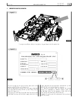
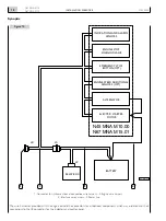
N45 MNA M10
N67 MNA M15
MAY 2006
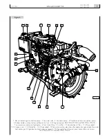
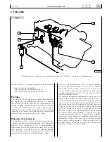
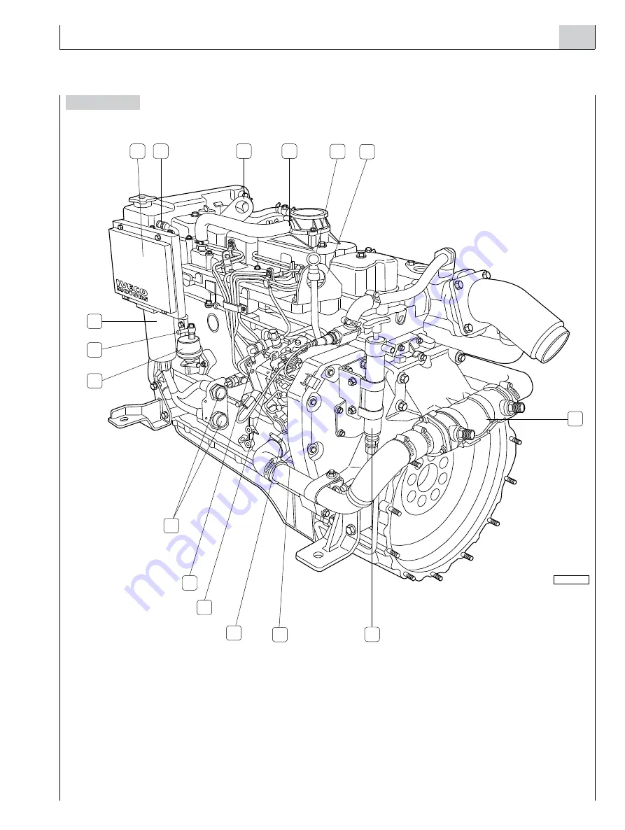
Figure 4
1. Manual lubricating oil extraction pump - 2. Sea-water inlet - 3. Sea-water pump - 4. Throttle lever lever on injection pump -
5. Rubber holder junction for fuel outflow to the tank - 6. Wiring connectors
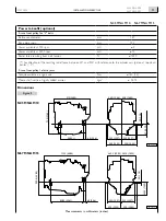
N45 MNA M10.00 and N67 MNA M15.00
-
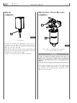
7. Low pressure mechanical feed pump - 8. Fuel intake fitting - 9. Fuel filter - 10. Combustion air filter - 11. Lifting eyebolt -
12. Oil vapours vent - 13. Oil dipstick - 14. Lifting eyebolt - 15. Sea-water junction pipe from after-cooler to engine coolant/sea-water
heat exchanger (Oil gearbox heat exchanger, on request) - 16. Connector for instrument panel connection wire harness
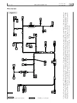
N45 MNA M10.01 and N67 MNA M15.01
.
06_606_N
10
4
3
2
5
6
9
7
1
12
13
11
8
14
15
16


