background image

NEF E

NGINE

N60 ENT M37

T

ECHNICAL AND

R

EPAIR

M

ANUAL

TECHNOLOGIC

AL EXCELLENCE

Summary of Contents for N60 ENT M37

Page 1: ...NEF ENGINE N60 ENT M37 TECHNICAL AND REPAIR MANUAL T E C H N O L O G I C A L E X C E L L E N C E ...

Page 2: ...than those stat ed by the manufacturer IVECO MOTORS is available beforehand to examine requirements for special installations if any In particular Use of unsuitable fuels and oils may compromise the engine s regular operation reducing its performance reli ability and working life Exclusive use of IVECO Original Parts is a necessary condition to maintain the engine in its original integrity Any tam...

Page 3: ...are intended for sales personnel to provide them with exact knowledge of the product s characteristics and enable them to meet Customer s demands with preci sion as well ad for yard personnel to help them design and complete a correct installation Remainders sections are meant for personnel tasked with conducting ordinary and extraordinary maintenance with an attentive consultation of the chapter ...

Page 4: ...N60 ENT M37 IV APRIL 2004 ...

Page 5: ...e 17 COMBUSTION AIR INTAKE AND EXHAUST SYSTEM 18 Comburent air filter 19 Turbocompressor 19 Air seawater heat exchanger 19 COOLING FRESH WATER CLOSED LOOP 20 Exhaust manifold cooling 21 Thermostatic valve 22 Water pump 22 Additional expansion tank 22 SEA WATER OPEN COOLING LOOP 23 Sea water Pump 24 Sea water coolant heat exchanger 24 ENGINE OIL LUBRICATION LOOP 25 Gear Pump 26 Filter bracket 26 Oi...

Page 6: ... temperature sensor 44 Atmospheric pressure sensor 44 Oil pressure temperature sensor 45 Crankshaft sensor 45 Camshaft sensor 46 Coolant temperature sensor 46 Fuel temperature sensor 47 Fuel pressure sensor 47 Pressure control solenoid 48 Throttle lever position 48 SYSTEM FUNCTIONS 49 Run up 49 Starting 49 Metering and fuel injection 49 Injection advance management 49 Pre injection 50 Injection pr...

Page 7: ...G DATA from january 2004 04_004_N 04_007_N 1 2 Viale dell Industria 15 17 20010 Pregnana Mil se MI ITALY ENGINE TYPE ENGINE DWG ENGINE S N COMMERC TYPE VERSION POWER SET CODE HOMOLOGATION N ENGINE FAMILY POWER KW AND SPEED RPM YEAR OF BUILD S p A 04_002_N Figure 2 Figure 3 Figure 1 ...

Page 8: ...The commercial code therefore cannot be used for technical purposes to recognize the engine s components this purpose is served by the ENGINE S N N 60 E N T M 37 1 0 ENGINE FAMILY IDENTIFIER N NEF DISPLACEMENT 60 6000 cc NOMINAL FUEL SUPPLY E ELECTRONIC INJECTION BASE N NON STRUCTURAL AIR INTAKE T INTERCOOLED SUPERCHARGED APPLICATION M MARINE MAXIMUM PERFORMANCE LEVEL ACHIEVABLE 37 370 HP VERSION ...

Page 9: ... its application and power output level It is stamped on a side of crank case F 4 A E 0 6 8 6 B E 1 0 3 ENGINE FAMILY IDENTIFIER DESIGN ITERATION ENGINE NO OF STROKES AND CYLINDER DISPOSITION 0 4 STROKES VERTICAL NO OF CYLINDERS FUEL INJECTION 8 DIESEL TCA DIRECT INJECTION INTENDED USE 6 MARINE POWER RANGE B MAXIMUM POWER 370 HP E EMISSION FOR MARINE APPLICATION VARIANTS TO BASIC ENGINE ...

Page 10: ...haust gas and sea water discharge pipeline 7 Cap for engine coolant outlet to sanitary water heating system 8 Lifting eyebolts 9 Rocker arm cover 10 Oil refill cap 11 Coolant refill cap 12 Location of thermostatic valve 13 Engine coolant tank 14 Auxiliary belt automatic tensioner 15 Alternator 16 Cap for engine coolant discharge and recirculation from sanitary water heating system 17 Oil filter 17...

Page 11: ...ode 8 Oil vapor separator 9 Combustion air sea water heat exchanger 10 Location of sea water discharge cap 11 Manual lubricating oil extraction pump 12 Combustion air pressure and temperature sensor 13 Oil dipstick 14 Common rail distributor 15 Air filter clogging sensor 16 Cooled turbocharger 17 Sea water junction pipe from after cooler to engine coolant sea water heat exchanger 1 2 3 4 9 10 11 1...

Page 12: ... engines can be rigged by a mechanical pump or by a total electronic controlled Common Rail fuel supply system Every technical solution has been accurately devised so as to assure qualitative product perfection The configuration istself of the engine has been designed in such a way so as to facil itate access to each individual part and thus reducing main tenance time The cylinder head fitted with...

Page 13: ...fix tures to assemble and disassemble them Connecting Rods They are made in steel manufactured by pressing with small end oblique edged and cap separation obtained by fracture splitting technique The connecting rod half bearings are cast babbitt lining steel Every connecting rod is marked on the body and on the cap by a number that identifies their coupling and the cylinder into where has to be as...

Page 14: ...nt geom etry 1st piston ring with trapezoidal section and ceramic chrome plating 2nd piston ring with a torsional conical rectangular seal 3rd piston ring with double oil scraper with internal spring Timing system driving gear Timing system driving gear machine members are push rods and rockers type with a camshaft that is located in the crankcase and set into rotation directly by the crankshaft 1...

Page 15: ...haft with direct coupling to straight toothed wheel The toothed wheel keyed on the timing camshaft has 6 1 slots for camshaft sensors 11 enabling the generation of the electric signals needed for the engine control system N60 ENT M37 OVERVIEW 1 15 APRIL 2004 1 Spindle 2 Rocker 3 Adjuster screw 4 Rod 5 Bridge 6 Cotters 7 Cup 8 Spring 9 Tappet 10 Camshaft 11 Holes for camshaft sensor Figure 12 04_01...

Page 16: ...haust manifold Induction manifold On the top part of the head the chassis to which are fastned the connectors of the wiring harness for the control of elec tro injectors has been secured N60 ENT M37 OVERVIEW 1 16 APRIL 2004 Cylinder head Figure 13 1 Electro injector 2 Electro injector electric connection terminal 3 Thermostat valve 4 Induction manifold 5 Fuel filling pipe to the injector 6 Cylinde...

Page 17: ...1 Crankshaft 2 Engine coolant pump pulley 3 Stationary guide pulley 4 Alternator pulley 5 Spring tightner 6 Stationary guide pulley Motion to ancillary machine members is transmitted by a Poly V belt put under tension by a gauged spring 5 Stationary guide pulley 3 is located between the alternator pulley and the engine coolant pump pulley in order to pro vide an adequate contact surface on the lat...

Page 18: ... a fuel metering adequate to the density of the intaken comburent air and an optimum management of the injection advance The exhaust gas flow into the exhaust terminal and where foreseen riser mixed seawater to be expelled N60 ENT M37 OVERVIEW 1 18 APRIL 2004 1 Air filter 2 Turbocompressor 3 Exhaust gas inlet in turbine 4 Heat exchanger air sea water 5 Seawater outlet pipe from the exchangers 6 Ex...

Page 19: ...ir inlet 5 Comburent air outlet 6 Condensate drainage hole The flow of water coming from the sea water pump goes through the tube bundle 3 and by going through it absorbs some of the heat of the overheated air of the turbosuper charge passing through the exchanger coming from the tur bocompressor 4 The outlet water 1 is conveyed towards the heat exchang er fresh water sea water while the turbosupe...

Page 20: ...t to the sea water to re enter then to the inlet of the pump The coolant before going through the crankcase cools down the engine oil that goes through its own heat exchanger 4 Some of this oil comes out from the rear branchpipe to lap on the turbine and cools down the volute 7 and goes through the exhaust manifold cavity in order to reduce its temperature as it is foreseen by the nautical regulat...

Page 21: ...d 4 Thermostatic valve exchanger water water connector 5 Degassing piping 6 Plug with pressure valve 7 Thermostatic valve 8 Water pump manifold inlet Figure 21 Exhaust manifold cooling 04_029_N 1 8 2 6 3 4 5 7 Engine coolant through exhaust manifold Hot engine coolant through coolant exchanger Sea water ...

Page 22: ...nd is set into rotation by poli V belt Additional expansion tank In some cases an additional tank may be fitted with the pur pose to increase the available expansion volume the con nection to the main tank can be made by a pipe fitted on the hose holder of the union pipe overflow The plug of this tank has to be equipped with a pressure relief valve to enable liquid downflow while the engine is coo...

Page 23: ...eat exchanger if fitted reaches the sea water fresh water heat exchanger removing the heat yielded by the engine and conveyed by coolant temperature control is car ried out by the thermostatic valve The water before being let into the sea drainage duct laps onto and cools down the riser exhaust gas outlet where comes out of the boat with the latter N60 ENT M37 OVERVIEW 1 23 APRIL 2004 1 Sea water ...

Page 24: ...lant coming from thermostatic valve goes into the exchanger 3 and laps on the tube bundle where the sea water flow coming from the supercharging air heat exchanger 1 runs through the engine coolant cooled down goes through the manifold leading to the induction of the centrifugal pump 4 The sea water coming out from the exchanger 2 is sent to the outlet N60 ENT M37 OVERVIEW 1 24 APRIL 2004 Figure 2...

Page 25: ...igned to the lubrication of the machine members bench bearings con necting rods and timing push rods and rockers the lubrica tion of spindles and toothed wheels to actuate ancillary machine members is obtained by dedicated ducts The flows afterwards converge by gravity into oil sump The oil for the lubrication of the spindle of the turbocompressor rotors is drawn immediately after the oil filter a...

Page 26: ...x 3 Oil vapour filter unit 4 Flow limiter valve 5 Residual vapours to engine intake 6 Centrifugal separator The oil vapours which generate inside the engine go through the centrifugal gas separator machined in the upper part of the rocker lid where some of them condensate and return to the oil sump through the dedicated ducts Residual vapours due to higher pressure are pushed to the timing gear bo...

Page 27: ...gine except the pre filter N60 ENT M37 OVERVIEW 1 27 APRIL 2004 Figure 32 1 Fuel filter 2 Common rail 3 Electro injector 4 Electro injector return loop pressurization valve 5 Rail overpressure valve 6 High and low pressure pump 7 Priming pump 8 Settling pre filter High pressure Low pressure 1 2 3 5 4 8 6 04_072_N 7 FUEL LINE ...

Page 28: ...internal pressure sensor 5 enables EDC central unit to measure its value and to control in loop the control solenoid valve in order to always obtain the high pressure value required by the injection map ping while the overpressure valve in the event of an anom aly on the control system protects the hydraulic system components limiting the pressure in the rail at the value of 1750 bar The electroin...

Page 29: ...n reflux from the electroinjectors to flow into the manifold 10 located on the filter bracket from which a pipe leads to the fuel tank 9 In parallel to the feed mechanical pump two unidirectional valves are positioned Valve 13 when the pressure at the fuel inlet overcomes the limit value allowed recirculate the fuel excess to the inlet of the pump itself When the engine is not rotating a by pass v...

Page 30: ...s well as a good separation of water from fuel The fuel filter is located on the crankcase in the line between feed pump and high pressure pump Connectors B C E join into one duct which works as manifold of the fuel recir culating towards the tank The manifold is entirely separated from the hydraulic line of the filter On the support are posi tioned the fuel temperature sensor and the resistor of ...

Page 31: ...d The positioning of the pump does not require timing as the injections management is entirely electronically controlled N60 ENT M37 OVERVIEW 1 31 APRIL 2004 Figure 36 1 Connector fuel outlet to rail 2 High pressure pump 3 Pressure control solenoid 4 Fuel inlet connector from filter 5 Fuel outlet connector to recirculation manifold 6 Fuel inlet from tank 7 Fuel outlet connector from low pressure p...

Page 32: ...Fuel inlet from tank B Fuel outlet to filter 1 Recirculation valve 2 By pass valve In the case of overpressure at the outlet figure 38 recircula tion valve comes into action The existing pressure overcoming the spring valve elastic strength 1 connects the outlet with the inlet through duct 2 recirculating the fuel in excess inside the pump and keep ing a pressure rating equal to that one of the se...

Page 33: ...e line as an example by means of the manual pump located on the pre filter With the engine not in rotation due to the pressure in the inlet the by pass valve 2 opens up enabling the fuel to flow towards the filter A Fuel inlet from tank B Fuel oulet to filter 1 Recirculation valve 2 By pass valve Figure 39 04_045_N 1 2 A B ...

Page 34: ...on dition The Central Unit sends to the controller a PWM control sig nal in order to choke in a greater or lesser way the inlet sec tion of the fuel to the high pressure pump This component cannot be replaced individually and there fore must not be disassembled Low pressure limiter valve Assembled in parallel to the pressure control solenoid valve has the function to keep inlet pressure constant t...

Page 35: ... limiter valve is in close position The clearance among the internal parts enables the blow by of the fuel used to lubricate the pump towards the exhaust 7 N60 ENT M37 OVERVIEW 1 35 APRIL 2004 Figure 42 04_017_N Pressure control with engine at maximum rating 1 Coil 2 Nucleus 3 Preloading spring 4 Spear valve 5 High pressure pump feed 6 Fuel inlet from filter 7 Fuel backflow form the high pressure ...

Page 36: ...d is in maximum choking as the common rail has to be kept at relatively low pressure from 350 to 400 bar The cylinder 8 of the low pressure limiter valve which controls the opening of the exhaust duct is in the maximum opening position in order to allow the fuel in excessto backflow to the exhaust 9 Figure 43 Pressure control with engine at minimum rating 1 Coil 2 Nucleus 3 Preloading spring 4 Spe...

Page 37: ... control solenoid 7 Control exhaust duct 8 Low pressure limiter valve 9 Fuel feed duct from filter 10 Fuel outlet In the section of figure 46 the low pressure fuel paths inside the pump are represented Pumping feed main duct 4 pumping feed ducts 1 3 6 ducts used for pump lubrica tion 2 pressure control valve 5 low pressure limiter valve 8 and fuel exhaust 10 are outlined Pump shaft is lubricated b...

Page 38: ...let from the pump with connector for high pressure piping for common rail In the section of figure 47 the fuel flow through the pump ing outlet ducts is represented N60 ENT M37 OVERVIEW 1 38 APRIL 2004 04_050_N Figure 47 1 2 3 sez A A ...

Page 39: ...ompo nents in case of malfunction of the rail pressure sensor or of the pump pressure control causes and excessive pressure increase in the high pressure system It is of a mechanical type and it has a double operating threshold 1750 bar and 800 bar In the case in the high pressure system 1750 bar is reached the valve comes into action initially as a normal one stage to let the fuel backflow and th...

Page 40: ...ng rod and nozzle and by the control solenoid made up by the coil and the pilot valve The solenoid controls the rise of the metering rod of the spray nozzle N60 ENT M37 OVERVIEW 1 40 APRIL 2004 1 Pressure rod 2 Metering rod 3 Nozzle 4 Coil 5 Pilot Valve 6 Ball valve 7 Control area 8 Pressure chamber 9 Control volume 10 Feed control duct 11 Control fuel outlet 12 Electric connection 13 Spring Elect...

Page 41: ...jection ceases by disenergizing the coil The ball valve goes back into the rest position to recreate an equilibrium of forces such as to make the metering rod going back to close position and stop the injection N60 ENT M37 OVERVIEW 1 41 APRIL 2004 1 Pressure rod 2 Metering rod 3 Nozzle 4 Coil 5 Pilot Valve 6 Ball valve 7 Control area 8 Pressure chamber 9 Control volume 10 Feed duct control 11 Cont...

Page 42: ... have the characteristics foreseen i e analogue to those used to make up the mapping of the injection timing Injectors do not need calibration and due to the high accu racy degree of its components and the complexity of their assembly no replacement of any spare part of which they are made of has been foreseen Pressurization valve of the electro injector backflow A To the tank B From the electro i...

Page 43: ... pressure temperature sensor 5 Timing sensor 6 Pressure control solenoid valve 7 Fuel filter with temperature sensor and electric heater 8 ECU EDC 9 Throttle control position sensor 10 Crankshaft sensor 11 Oil temperature pressure sensor Figure 53 04_058_N 2 3 4 5 6 7 8 1 11 10 9 EDC 7 SYSTEM ELECTRONIC AND ELECTRIC MAIN COMPONENTS ...

Page 44: ...s the electro injectors and the system actuators Air pressure temperature sensor It integrates a temperature sensor and a pressure one Positioned at the entrance of the intake manifod produces a signal that is proportional to the absolute pressure value of the intaken air and supercharged This information together with that one of the temperature enables to adequate time and advance to the density...

Page 45: ... circuit produced inside the cranckshaft by the presence of a permanent magnet It faces the pulley keyed on the crankshaft to detect the passage of 58 tooths every revolution The number of 58 tooths has been derived by a constant pitch of 6 which would lead to a total of 60 tooths 2 of which have been eliminated to generate an asimmetry of the signal that ECU EDC uses as crankshaft positioning ref...

Page 46: ... to terminal 1 and 2 and has a resistance of about 900 Ω It is connected to ECU EDC by pins A24 e A25 Terminal 3 is connected to electric shielding and is insulated from sensor Coolant temperature sensor It is a resistor with negative temperature coefficient and is positioned on the cylinder head at a short distance from the thermostatic valve It provides the indication of the metering and the adv...

Page 47: ...mance of the engine The ECU activates the relay for the filter heating element with a fuel temperature 0 C and heats up 5 C Temperature sensor has a resistance of about 2 5 k Ω at 20 C It is connected to ECU EDC by pins A18 and A36 Fuel pressure sensor It is assembled on one end of the rail and provides the fuel instantaneous pressure value necessary to assess the injec tion time span applied to t...

Page 48: ...on for the reckoning of the fuel amount to be injected It is operated by the linkage of the controls on bridge or assisted produces in output a potentiometric variation of the voltage which supplies it in relation to the position where the throttle lever is set A simultaneous safety indication is provided by the internal switch to confirm the acceleration position minimum out of minimum Such an in...

Page 49: ...g procedure is concluded Metering and fuel injection It is carried out by the span of time of the injectors electric control fed by the pressurized fuel in the accumulator time sharing Fuel pressure in the time sharing apparatus is made to change according to the performance goals required from the engine The primary datum of the amount of fuel to be injected is calculated according to the informa...

Page 50: ...ted on the instrument and control panel it is direct ly controlled by EDC system from the central unit It is nor mally off it will come on for an instant immediately after hav ing supplied the system by means of an efficiency test If lit EDC indicator states a likely anomaly of the injection sys tem or an irregular engine operation or of one of its machine members Fuel Heating It assures a correct...

Page 51: ...terised by the delay in deenergizing the main supply solenoid con tained inside ECU EDC During this phase the central unit is still powered for some seconds during which the data that have characterised the optimized management of the engine up to that moment are transferred from the main volatile memory into the EEPROM non volatile memory these data will then be available for the next starting Th...

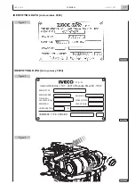
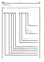
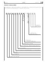
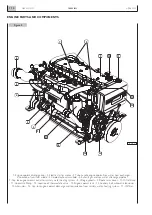
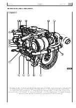
Page 52: ...N60 ENT M37 OVERVIEW 1 52 APRIL 2004 ...

Page 53: ...SECTION 2 TECHNICAL DATA Page PERFORMANCE 55 GENERAL SPECIFICATIONS 57 Dimensions 59 N60 ENT M37 TECHNICAL DATA 2 53 APRIL 2004 ...

Page 54: ...N60 ENT M37 TECHNICAL DATA 2 54 APRIL 2004 ...

Page 55: ...Engine utilization Use of maximum power limited to 10 of the time Cruising speed at engine rpm 90 of nominal calibration rpm Operat ing limit 1 000 hours year Definition of calibrations and operating limits for military and government agencies according to con tractual specifications Nominal maximum power kW HP rpm 242 330 1900 Nominal maximum torque Nm kgm rpm 1001 102 1900 Intermediate Service C...

Page 56: ... Power Takeoffs Optional 2 throated Front Pulley for V belts Reference diameter mm 187 Throat size mm 12 7 Power available 900 rpm kW HP 6 8 1 Power available 1800 rpm kW HP 12 16 3 Radial force given by belts tension N 1340 Direction of radial force from 60 to 300 referred to cylinder axis piston at Tdc 0 3 throated Front Pulley Elastic Joint Available torque in crank axis Nm kgm 150 15 Moment of...

Page 57: ...re bar Lubrication Oil type SAE 15 W40 E 3 Oil compliant with specifications ACEA E3 API CF4 MIL L2104E F Total oil capacity on first filling liters kg 16 5 14 8 Total oil capacity with sump at minimum level liters kg 9 8 1 Total oil capacity with sump at top level liters kg 14 5 13 Oil pressure warm engine minimum idling rpm bar 1 2 Oil pressure warm engine maximum rpm bar 3 8 Maximum allowed tem...

Page 58: ...forced circulation Water pump self priming with neoprene impeller Sea water pump height above sea level m 2 Max pump capacity liters h 12000 Exhaust gas expulsion Standard mixed with sea water Electrical system Nominal voltage V dc 12 Self regulated alternator Voltage V dc 14 Maximum current intensity A 90 Electrical starter motor Nominal voltage V dc 12 Absorbed electrical power W 4000 Recommende...

Page 59: ...N60 ENT M37 TECHNICAL DATA 2 59 APRIL 2004 177 6 96 840 33 07 1350 53 15 243 9 57 610 24 01 850 33 46 780 30 70 45 1 77 Figure 5 Dimensions Measurements in millimeters inches 04_070_N ...

Page 60: ...N60 ENT M37 TECHNICAL DATA 2 60 APRIL 2004 ...

Page 61: ...box connectors 71 CONNECTIONS OF THE CENTRAL ELECTRONIC UNIT ECU EDC 7 72 Identification of terminal function 72 Electro injectors connectors 76 EQUIPOTENTIAL CONNECTIONS TO ENGINE GROUND 77 ELECTRICAL DIAGRAMS 78 Wiring diagram key 78 Electrical equipment component code 79 Equipment versions until 10 2003 81 Equipment versions since 11 2003 85 CAN BUS converter module interface wiring 89 Suppleme...

Page 62: ...N60 ENT M37 ELECTRICAL EQUIPMENT 3 62 APRIL 2004 ...

Page 63: ...cument CAUTION Never use the wiring of the engine equipment to supply any other electrical appliance for the boat Information related to analogue and digital instrument and control panel and the related sensors are present in the N60 ENT M37 Installation Directive document Figure 1 1 2 4 3 6 7 8 5 10 9 15 04_073_N 1 Engine wiring 2 Indicator and control panel 3 Provided wire harness 4 JB Connectio...

Page 64: ...ith the engine include the connectors for all optional components which may ordered and their connections to the JB connector for the indicator and control panel JB JA JF1 JF2 A2 A1 A 04_235_N 3 4 1 2 INDICATIONS AND ALARMS SENSORS INDICATIONS AND ALARMS SENSORS ELECTRO INJECTORS EDC COMPONENTS ALTERNATOR BATTERY EDC RELAY BOX ELECTRIC STARTER MOTOR NEF ENT M37 GEAR BOX THROTTLE POSITION SENSOR Fi...

Page 65: ... 1 and 2 E2 Electro injectors cylinders 3 and 4 E3 Electro injectors cylinders 5 and 6 GG Alternator JB Connector for instrument panel connection wire harness JF1 JF2 Relay box MM Electric starter motor PA Throttle position sensor PF Heating element on fuel filter PR Rail pressure sensor SI Gear box oil temperature sensor VE Engine oil pressure temperature sensor for EDC VI High gear box oil press...

Page 66: ...ure sensor for gauge V Oil pressure sensor for gauge E1 Electro injectors cylinders 1 and 2 connector E2 Electro injectors cylinders 3 and 4 connector E3 Electro injectors cylinders 5 and 6 connector IN Electro injectors PA Throttle position sensor PF Heating element on fuel filter PR Rail pressure sensor VE Engine oil pressure temperature sensor for EDC ZH Pressure control solenoid valve 04_220_N...

Page 67: ...the B terminal of the alter nator to the positive 30 terminal of the electric starter motor to complete the recharge circuit must be achieved with a conductor having a cross section of at least 10 mm2 The connection of the electric equipment of the engine to the accumulator has to be carried out by the two eyed ter minals B and B present on the wiring harness CAUTION If magneto thermal protecting ...

Page 68: ...al nut B 12 15 Nm CHARACTERISTIC CURVES Specification Nominal voltage 14 V Nominal current max 90 A Rpm max 6000 rpm Current max at 1800 rpm 50 A Polarity Negative ground Rotation Clockwise viewed from pulley Belt Poli V Poles 12 Weight 5 7 kg Figure 6 Figure 7 04_223_N 100 90 80 70 60 50 40 30 20 10 0 0 1 2 3 4 5 6 7 8 Alternator speed rpm x 1000 Ambient temp 25 C Ambient temp 90 C Output current...

Page 69: ...0 C Water resistance Water spray test based on JIS D0203 SI Figure 8 Figure 9 V 13 12 11 10 9 8 7 6 5 4 3 2 1 0 RPM 2600 2400 2200 2000 1800 1600 1400 1200 1000 800 600 400 200 0 kW 65 60 55 50 45 40 35 30 25 20 15 10 5 0 Nm 130 120 110 100 90 80 70 60 50 40 30 20 10 0 04_225_N 04_226_N Engine electrical ground connection point CHARACTERISTIC CURVES 200 400 600 800 1000 1200 1400 1600 I A B V kW N...

Page 70: ...id 5 for connection with the computerized diagnostic tools prescribed by IVECO MOTORS see Section 4 This shall be installed and anchored in such a way as to dampen the vibrations and stresses occurring when under way and they shall be accessible during servicing operations and when underway Relays contained in the relay box K1 Fuel filter heater element power supply K2 Power supply to terminal 50 ...

Page 71: ...of the wire harness terminal coupling side N60 ENT M37 ELECTRICAL EQUIPMENT 3 71 APRIL 2004 Figure 12 Figure 13 5 15 25 35 1 2 3 11 12 13 21 22 23 31 32 33 4 14 24 34 16 26 20 30 40 17 18 19 27 28 29 37 38 39 36 6 7 8 9 10 3 1 2 9 15 21 7 8 13 19 14 20 6 12 18 24 5 4 11 10 16 17 23 22 04_214_N 04_216_N Figure 15 Figure 16 PIN 13 PIN 1 PIN 25 PIN 24 PIN 12 PIN 36 PIN 7 PIN 1 PIN 12 PIN 6 PIN 13 PIN...

Page 72: ...side connections Identification of terminal function EDC A Connector PIN ECU FUNCTION 1 Not used 2 Not used 3 Not used 4 Not used 5 Negative drive pressure control solenoid valve on the high pressure pump 6 Not used 7 Positive drive pressure control solenoid valve on the high pressure pump 8 Not used 9 Positive supply oil pressure temperature sensor 10 Positive supply combustion air pressure tempe...

Page 73: ...temperature sensor 36 Signal from coolant temperature sensor Identification of terminal function EDC A1 Connector PIN ECU CABLE COLOUR FUNCTION 1 Not used 2 Not used 3 red blue Injector cylinder 2 4 white purple Injector cylinder 3 5 white violet Iniettore cilindro 4 6 red white Iniettore cilindro 2 7 Not used 8 Not used 9 red green Injector cylinder 1 10 blue brown Injector cylinder 6 11 blue gre...

Page 74: ...d on relay box 20 Positive from K5 relay during cranking PIN ECU FUNCTION 21 Not used 22 Not used 23 Not used 24 Not used 25 Not used 26 Not used 27 Positive from blink code button 28 Positive for EDC faults indicator light 29 Not used 30 L diagnosis line 31 K diagnosis line 32 Not used 33 Not used 34 Not used 35 Not used 36 Positive for K1 relay control 37 Positivo for K2 relay control 38 Not use...

Page 75: ... used 60 Not used 61 Not used 62 Not used 63 Low oil pressure indicator control 64 EDC fault indicator control 65 High coolant temperature indicator control PIN ECU FUNCTION 66 Not used 67 Not used 68 Not used 69 Not used 70 Not used 71 Not used 72 Signal from idling switch sensor located in throttle position sensor 73 Not used 74 Resistor 3 3 k Ω balancing load 75 Not used 76 Not used 77 Not used...

Page 76: ... conditions met in that environment every couple of con ductor is braided to avoid the generation of electromagnet ic interferences Pay special attention to the phases of con nection of the terminals of the wiring of the electro injectors which have to take place among conductors spotless clean and applying the correct tightening torque Electro injectors connectors 1 2 1 2 1 2 1 2 1 2 1 2 4 3 1 2 ...

Page 77: ...r 1 Junction of the fresh water outlet pipe from the water water heat exchanger 2 Fresh water supply pipe to water water exchanger 3 Sea water supply pipe to water water exchanger CAUTION To enhance connection efficiency the screw threads and the surfaces in contact with the electrical terminals must be clean and not oxidized so thoroughly inspect and remove any impurities before each reinstallati...

Page 78: ...L ENGINE ROOM 30 50 JB 7 JA 14 JF1 36 15 JB 2 JA 12 JF1 25 JF1 8 JA 26 M A 5 JB 9 R3 D1 F2 K4 DK4 K3 DK3 SW2 STOP START 17 JF2 9 JF2 16 JF2 13 JF1 F1 5 6 T CA 38 JC 12 JC JC 7 JB 8 JA 15 JF2 15 JC 8 JH 10 JE 10 JH 4 JE 4 JC 2 JA 19 20 32 34 Figure 45 Component terminal Terminal connections Minimum cable cross section in mm2 Connection JC connector 8 terminal Component code or connector code Compon...

Page 79: ...push button on secondary panel GG alternator IN electro injector MC converter module for digital panel MM electric starter motor MS IVECO MOTORS indications and alarms module PA throttle position sensor PE emergency shut down push button optional installer s responsibility PF heating element on fuel filter PR rail pressure sensor QP main analog instrument panel QS secondary analog instrument panel...

Page 80: ...anel JE1 ON INTERFACE WIRE HARNESS FOR CONVERTER MODULE set for connection to the 2 main digital instrument panel JF1 relay box JF2 relay box JH ON SECONDARY ANALOG INSTRUMENT PANEL set for connection to the main analog instrument panel JH ON MAIN DIGITAL INSTRUMENT PANEL set for connection to the interface wire harness for converter module JO converter for digital panels Indicator lights EDC EDC ...

Page 81: ... JF1 21 JF1 31 JF1 R1 25 JA 28 4 JF1 27 JF1 22 JF1 38 JB 16 JA 12 JB 10 JA R4 DL1 EDC K1 K2 DK1 DK2 17 JA 1 JB F3 1 2 7 8 13 14 19 20 B A SW1 NORMAL ENGINE ROOM 30 50 JB 7 JA 14 JF1 37 15 JB 2 JA 12 JF1 13 JF1 9 JA 26 M A 5 JB 19 R3 D1 F2 K4 DK4 K3 DK3 SW2 STOP START 32 JF1 35 JF1 34 JF1 3 JF1 F1 5 11 JF2 17 18 23 24 T C D A B F E V U J1 F5 5 JF1 R2 6 1 26 33 36 JF1 38 JF1 7 K5 JF1 2 JF1 12 JB 3 J...

Page 82: ... 14 15 21 P U t R 1 3 4 2 10 28 29 19 P U t R 1 3 4 2 9 33 35 20 P U 1 2 3 27 12 H VE PR A1 17 18 36 34 25 24 2 1 3 B 56 23 30 2 1 3 C 57 6 3 1 2 IN2 9 13 1 2 IN1 14 5 1 2 IN4 4 12 1 2 IN3 15 10 1 2 IN6 11 16 1 2 IN5 85150 2 1 4 3 E1 2 1 4 3 E2 2 1 4 3 E3 1 2 JF2 7 8 13 14 19 20 39 JF1 4 1 7 12 13 5 11 JF2 17 18 23 24 F1 A F AC ...

Page 83: ... 34 40 85150 65 B 2 K 1 1 15 14 9 3 64 28 49 45 SI WI VI O 2 1 1 1 42 1 1 25 26 21 1 1 43 22 23 19 19 47 46 10 16 30 18 12 38 39 46 8 63 1 52 53 JF1 4 JF2 24 13 12 7 18 23 11 17 5 7 9 13 11 31 35 17 3 24 20 29 29 JB 10 37 11 1 1 JC F3 41 L P1 8 2 4 7 14 6 9 15 39 27 16 36 13 5 L L 3 2 1 33 JC 32 34 40 MS 12 45 42 25 26 21 43 22 23 1 9 9 19 19 47 46 30 18 38 19 8 7 10 13 15 2 3 31 35 17 3 24 20 29 ...

Page 84: ...A2 EDC 8 JA 9 37 11 13 14 15 12 8 2 4 7 14 6 9 15 39 27 16 36 8 13 5 1 1 7 JC 20 F3 19 14 8 13 2 1 L 8 2 4 7 14 6 9 15 39 27 16 36 13 5 MS 1 9 9 19 8 7 10 13 15 2 3 17 18 5 4 12 16 14 11 6 24 SAC SS SIFA EDC SATA SBPO AC JF2 6 B 2 34 34 CS MS 1 9 19 8 7 10 13 15 2 3 17 18 5 4 12 16 14 11 6 23 SAC SS SIFA EDC SATA SBPO JA 49 A2 EDC JD JD AS 1 2 3 4 6 5 8 7 10 9 11 12 12 11 10 9 7 8 5 6 3 4 2 1 P1 P...

Page 85: ...1 14 JF2 33 JF1 R1 25 JA 28 6 JF1 1 JF1 3 JF1 38 JB 16 JA 12 JB 10 JA R4 DL1 EDC K1 K2 DK1 DK2 17 JA 1 JB F3 1 7 13 B A SW1 NORMAL ENGINE ROOM 30 50 JB 7 JA 14 JF1 36 15 JB 2 JA 12 JF1 25 JF1 8 JA 26 M A 5 JB 9 R3 D1 F2 K4 DK4 K3 DK3 SW2 STOP START 17 JF2 9 JF2 16 JF2 13 JF1 F1 5 6 JF2 10 11 T C D A B F E V U J1 F5 30 JF1 R2 29 26 16 18 4 JF1 35 JF1 17 K5 JF1 14 JF1 2 JB 3 JA 11 JA 7 9 JB 31 35 27...

Page 86: ...A2 1 2 ZH 3 9 14 15 21 P U t R 1 3 4 2 10 28 29 19 P U t R 1 3 4 2 9 33 35 20 P U 1 2 3 27 12 H VE PR A1 17 18 36 34 25 24 2 1 3 B 23 30 2 1 3 C 6 3 1 2 IN2 9 13 1 2 IN1 14 5 1 2 IN4 4 12 1 2 IN3 15 10 1 2 IN6 11 16 1 2 IN5 85150 2 1 4 3 E1 2 1 4 3 E2 2 1 4 3 E3 1 7 JF2 13 39 JF1 6 1 7 12 13 5 6 JF2 10 11 F1 A F AC ...

Page 87: ...5 14 9 3 64 28 49 45 SI WI VI O 2 1 1 1 42 1 1 25 26 21 1 1 43 22 23 19 19 47 46 10 16 30 18 12 38 39 46 8 63 1 52 53 JF1 6 JF2 13 12 7 5 10 6 11 7 9 13 11 31 35 17 3 24 20 29 28 JB 10 37 11 1 1 JC F3 41 L P1 8 2 4 7 14 6 9 15 39 27 16 36 13 5 L L 3 2 1 33 JC 32 34 40 MS 12 45 42 25 26 21 43 22 23 1 9 9 19 19 47 46 30 18 38 19 8 7 10 13 15 2 3 31 35 17 3 24 20 29 28 17 18 5 4 12 16 14 11 JC 10 37 ...

Page 88: ... JA JB 26 32 JF1 20 DK5 K5 A2 EDC 8 JA 20 36 15 25 14 15 12 8 2 4 7 14 6 9 15 39 27 16 36 8 13 5 1 1 JC 13 F3 7 1 L 8 2 4 7 14 6 9 15 39 27 16 36 13 5 MS 1 9 9 19 8 7 10 13 15 2 3 17 18 5 4 12 16 14 11 6 24 AC JF2 6 B 2 34 34 CS MS 1 9 19 8 7 10 13 15 2 3 17 18 5 4 12 16 14 11 6 23 JA 49 A2 EDC JD JD AS 1 2 3 4 6 5 8 7 10 9 11 12 12 11 10 9 7 8 5 6 3 4 2 1 P1 P1 AQ JE JH QS QP ENGINE ROOM NORMAL S...

Page 89: ... 14 12 1 0 1 0 1 0 1 0 1 0 1 0 6 10 11 9 8 7 5 4 2 3 1 0 5 0 5 1 0 1 0 1 0 1 0 2 5 1 18 1 0 0 5 0 5 1 0 1 0 1 0 1 0 1 0 2 3 4 5 6 7 8 9 1 0 1 0 1 0 1 0 10 11 12 13 16 14 15 17 1 0 1 0 1 0 1 0 1 0 1 0 1 0 22 20 19 21 24 23 25 26 1 0 1 0 1 0 1 0 1 0 1 0 1 0 27 28 29 30 33 32 31 34 JE1 1 0 1 0 1 0 1 0 2 3 4 1 1 0 1 0 36 JD Connector key JB instrument panel engine side JD external throttle control JE ...

Page 90: ...6 GG1 B AC2 10 10 GG2 B 2 2 MM JA 29 29 JA IE1 IE2 M 30 50 6 70 BAT 6 AC1 MM BAT 10 GG B 10 70 JA 29 30 86 87 85 AC2 10 10 RL 2 Single engine installation Two engines installation Key AC1 Main Battery AC2 Battery for auxiliary services IE1 Engine 1 electrical system IE2 Engine 2 electrical system RL Relay 50A max Electrical power supply for services ...

Page 91: ...rument 97 Identifier 97 Fault Memory 98 Parameter reading 98 Active diagnostics 98 MAJOR DIAGNOSTIC ACTIONS 99 Checking pressure in fuel supply line 99 Checking component resistance value 99 Checking line insulation 99 REFERENCE VALUES 100 For non hardwired sensors 100 For wired sensors powered by the ECU 101 GUIDE TO BLINK CODE DIAGNOSING 102 GUIDE TO SYMPTOM DIAGNOSING 112 N60 ENT M37 DIAGNOSTIC...

Page 92: ...N60 ENT M37 DIAGNOSTICS 4 92 APRIL 2004 ...

Page 93: ...ditionalinformation required to determine the origin of the fault Every time a problem is notified and its existence is ascer tained you must query the electronic unit in one of the ways indicated and then proceed with troubleshooting with tests and measurements to obtain a picture of the overall oper ating conditions and identify the real causes of the fault If the electronic unit provides no ind...

Page 94: ... pressed and comes off about 1 second after its release without any subsequent blinking NOTE The blink code diagnostic procedure provides indications about current anomalies as well as past anomalies that are no longer present when the diagnosis is carried out therefore it is absolutely mandatory at the end of every repair operation to erase the error memory to prevent anomalies whose cause has al...

Page 95: ...ter 2 9 on not significant in marine applications Engine Area 2 3 1 off cylinder balancing 1 3 2 off cylinder balancing 5 3 3 off cylinder balancing 3 3 4 off cylinder balancing 6 3 5 off cylinder balancing 2 3 6 off cylinder balancing 4 3 7 on battery voltage 3 8 off not significant in marine applications 3 9 on not significant in marine applications 4 6 on not significant in marine applications ...

Page 96: ...nal 6 8 off synchronism trouble with diagnosis tool Fuel pressure 8 1 blinking fuel pressure control x 8 2 blinking fuel pressure signal x 8 3 blinking pressure regulator solenoid valve x 8 4 blinking twin stage valve tripping x 8 5 blinking MIN MAX rail pressure error ENGINE STOP Electronic unit 9 3 blinking not significant in marine applications x 9 4 on main relay 9 6 blinking after run procedu...

Page 97: ...onfirm it with the key The second screen shows information about the software version of the selected application To start the actual diagnosis procedure press the key CAUTION The two arrows when present signal that other options are available but not displayed To display them use the arrows on the keypad To access the diagnosing procedure press the 1 key and con firm with the key The instrument d...

Page 98: ...emperature Supercharging pressure Ambient pressure Flywheel Camshaft Quantity of air taken in Engine Runaway engine Injectors Pre post heating control system Relays Main Fuel filter heater Power supply voltage Indicator lights EDC Central Unit Invalid data set Incorrect data storage Internal fault Gate Array Sensors power supply Internal fault re initialization Incorrect engine shutdown Defective ...

Page 99: ...m its wiring or connected only to the instru ment set as ohmmeter on the appropriate end of scale value see REFERENCE VALUE table in the pages that follow At the end restore the correct connection Checking line insulation Ensure that the system is not powered The measurement must be taken on each individual conductor isolated from all the components to which it is normally connected The mea sureme...

Page 100: ...nly to the reference component The actual measurement of limited values of resistance requires use of instruments with the SELF ZEROING function or if these are not available subtract from the read value the short circuit value of the instrument prods Measurements closest to reality are taken including the wiring from the ECU to the sensor Always check the continuity of the SHIELD conductor from t...

Page 101: ... Combustion air absolute pressure sensor signal A21 A28 Engine running 0 9 1 1 Vcc 600 giri min Combustion air absolute pressure sensor power supply A10 A21 Panel key ON 4 5 5 5 Vcc Fuel pressure sensor power supply A12 A20 Panel key ON 4 5 5 5 Vcc Lubrication oil pressure sensor power supply A9 A19 Panel key ON 4 5 5 5 Vcc Safety signal Lever in position 0 4 Vcc from throttle A2 19 A2 72 position...

Page 102: ...t check the integrity of the idling switch switching ON OFF If the switch is integral search for a break in the wiring between the throttle connector wiring side and the EDC connector pin A2 19 e A2 72 Read measurable parameters with the diagnosis instrument to verify the potentiometer does not work properly signal doesn t change between 0 and 100 Use a multimeter to check the integrity of the pot...

Page 103: ... the wiring between the sensor connector and EDC connector pin A 18 e A 36 Read measurable parameters with the diagnosis instrument with this error the turbocharging air temperature will be fixed at 20 C Check the integrity of the sensor R approx 2 5 kΩ at 20 C between its pins 1 and 2 If the sensor is integral check the wiring between the sensor connector and EDC connector A 21 e A 29 Read measur...

Page 104: ...ters with diagnosis instrument If the absolute pressure datum is fixed at 60 mbar or it is not consis tent measure by multimeter on a powered on sensor the supply voltage value U 5 V 10 If the value is consistent check wiring between the component and EDC Central Unit on pins A 10 A 21 e A 28 Read measurable parameters with diagnosis instrument If the fuel temperature datum is fixed at 120 or it i...

Page 105: ...njector delivery drift ing from characteristics or pressure decay in cylinder Electroinjector delivery drift ing from characteristics or pressure decay in cylinder Electroinjector delivery drift ing from characteristics or pressure decay in cylinder Electroinjector delivery drift ing from characteristics or pressure decay in cylinder Call IVECO MOTORS and follow their instructions Call IVECO MOTOR...

Page 106: ...tors on the injec tor solenoid valve 1 5 Nm Check the integrity of the injector coil cylinder 5 R 0 3 Ω 10 and ground insulation replace the injector if defective If the coil is integral check the wiring between the solenoid valve and EDC connector pin A2 3 e A2 6 Check correct tightness to torque of the connectors on the injec tor solenoid valve 1 5 Nm Check the integrity of the injector coil cyl...

Page 107: ...ulation replace the injector if defective If the coil is integral check the wiring between the solenoid valve and EDC connector pin A2 5 e A2 14 Check correct tightness to torque of the connectors on the injec tor solenoid valve 1 5 Nm Check the integrity of the injector coil cylinder 4 R 0 3 Ω 10 and ground insulation replace the injector if defective If the coil is integral check the wiring betw...

Page 108: ... 5 6 proceed with the cheks advised reset memory and start the engine again If the anomaly persists Call IVECO MOTORS and follow their instruc tions Check the sensor is clean and secured correctly Check the integrity of the sensor R 900 Ω 10 at 20 C and ground insulation replace it if defective If the sensor is integral check the wiring between the sensor and EDC connector pin A 24 e A 25 Check th...

Page 109: ...ve or open circuit Pressure measured on rail is very different from that one calculated by EDC unit Pos sible air blow by or loss in the fuel line Wire connections shorted or shorted to ground or shorted to positive or open circuit or defective compo nent Delete the fault memory and restart the engine Diagnosis active with the diagnosis instrument If the result is neg ative check wiring between th...

Page 110: ...ol unit each time the engine stops Measure by multimeter the solenoid resistance value R 2 8 Ω 10 and insulation from ground If component is efficient check wiring between component and EDC unit on pins A2 5 e A2 7 Check connector efficiency If associated with code 8 1 check 8 1 8 2 e 8 3 Replace the two stage overpressure valve After its replacement carry out checks 8 2 and 8 3 With key in positi...

Page 111: ...l unit fault Delete the fault memory and try again if the error remains call IVECO MOTORS and follow their instructions Possible association with error codes of sensor powered by EDC central unit GUIDE TO BLINK CODE DIAGNOSING Blink EDC Code light System reactions Possible cause Recommended tests or action Notes ...

Page 112: ...Faulty terminal connections Malfunction Faulty terminal connections Supply fuse inside box relay Batteries malfunction B and B electrical connections Wiring Malfunction Faulty terminal connections Priming incorrect Incorrect filling air in fuel circuit Clogged Malfunction Recharge disconnecting system wiring Clean check tighten terminals Check clean tighten terminals Check connections to positive ...

Page 113: ...tatic valve Coolant sea water heat exchanger Air filter Cylinder head gasket Below MIN level Incorrect tension Wear Malfunction Locked closed or only partially open Clogged Clogged Compression leaking from cylinder head gasket Check for leaks Top up correct level Check tension Replace Check for liquid leakage on drive belt Replace Check belt tension Check for liquid leakage on drive belt Replace C...

Page 114: ...d open Clogged Losses along the cooled manifold before the turbine Clogged Inefficient Bearings inefficient Wear Incorrect timing Excessive or nil clearance Output signal too low below to the pressure value Output signal too high Replace clogged filters Check intake seals Check pressure relief valve on the fuel gear pump Check the integrity of the fuel gear pump The non operating electro injector ...

Page 115: ...der gasket Water in intake system from air sea water heat exchanger Water in fuel Excessive oil consumption Oil leaking in turbocharger Oil leaking from valve guides Fuel reservoir empty Float in non accurate position Clogged See item Poor performance Faulty terminal connections B and B electrical connections Wiring Check voltage on the fuel filter heater con nector Check fresh water level Check f...

Page 116: ...N60 ENT M37 DIAGNOSTICS 4 116 APRIL 2004 ...

Page 117: ...TENANCE Page PERIODICITY OF CHECKS AND MAINTENANCE OPERATIONS 119 PREPARING THE ENGINE FOR LONG IDLE PERIODS 121 ENGINE S FIRST START RESTORING NORMAL OPERATING CONDITIONS 121 N60 ENT M37 MAINTENANCE 5 117 APRIL 2004 ...

Page 118: ...N60 ENT M37 MAINTENANCE 5 118 APRIL 2004 ...

Page 119: ...lectrolyte level in batteries 1 Check condition of oil vapor filter Periodic maintenance operations Periodicity Every 150 300 600 900 1200 Annual start hours hours hours hours hours 2 Clean air filter s 1 Check belt tension and conditions Check zinc anode corrosion condition 4 Restore battery electrolyte level Drain draw water and condensations from tank s 1 Replace engine lubricating oil after fi...

Page 120: ...e pre filter is provided with a water presence detector if the presence of water is detected drain the water from the appropriate drain and if the light stays lighted replace the filter 4 If zinc corrosion exceeds 50 of its volume replace it 5 Instructions provided in Section 8 6 Combustion air sea water exchanger clean air side and water side Engine coolant sea water exchanger clean the sea water...

Page 121: ... not been mixed with antifreeze and corrosion inhibiting agents affixing tags to indicate that the operation has been carried out If external parts of the engine are to be protected spray pro tective liquid OVER 19 AR onto unpainted metal parts such as flywheel pulleys and others avoid spraying belts connec tor cables and electrical equipment 1 Drain the residual protective oil type 30 M from the ...

Page 122: ...N60 ENT M37 MAINTENANCE 5 122 APRIL 2004 ...

Page 123: ...VES CLEARANCE ADJUSTMENT 130 CLEANING THE ENGINE COOLANT SEA WATER HEAT EXCHANGER 131 CLEANING THE AIR SEA WATER HEAT EXCHANGER 132 REMOVE THE RING SEALING THE ENGINE S DRIVING SHAFT FROM THE FRONT COVER 133 REMOVE THE HOLDING RING OF THE FLYWHEEL COVER BOX 134 FITTING FLYWHEEL HOUSING BOX 135 FITTING REAR GEARBOX 135 DECOUPLING SEA WATER COMPONENTS 136 INSTRUCTIONS FOR DISEMBARKING THE ENGINE 138...

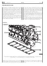
Page 124: ...N60 ENT M37 SERVICING OPERATIONS ON INSTALLED ENGINE 6 124 APRIL 2004 ...

Page 125: ...arts shall be supplied only if the following data are provided engine technical code and serial number part number as per spare parts catalog The information provided below refer to engine characteris tics which were current as of the publishing data The manufacturer reserves the right to make changes at any time and without advance notice to comply with technical or commercial requirements or to ...

Page 126: ... torque Ensure that the flywheel and camshaft sensors are posi tioned so they abut ensuring they are as close to per pendicular as possible with the bearing surface CAUTION Do not disconnect electrical connections without removing power from the circuits first Do not proceed with operating simulations with unsuitable tools and instruments Do not force measuring probes or mechanical tools into the ...

Page 127: ...he hydraulic accumulator it is necessary using a special wrench to prevent the flow limiters from turning Remove the screws 1 and disconnect the electro injector wiring mount 2 together with the gasket Remove the nuts 3 and take out the fuel manifolds 4 Loosen tappet adjustment fastening nuts 1 and unscrew the adjusters Remove the screws 2 remove the rocker assembly 3 consisting of bracket 6 rocke...

Page 128: ...der head seat so that the positioning ball 5 is coinciding with the relevant housing 4 CAUTION Disassembled fuel manifolds 2 must not be used again Replace with new items CAUTION During this operation figure 6 the injector 1 shall be moved so that the manifold 2 is properly inserted into the fuel inlet hole Use the torque wrench to tighten gradually and alternately the injector fastening screws 1 ...

Page 129: ...el filter Engine piping completing the low pressure fuel system is in metal construction Coupling is done using eye junctions secured using hexagonal screws Coupling water tightness is obtained using copper washers In case piping removal is necessary replace washers with new ones when reassembling Tighten low pressure junction screws with a torque of 12 Nm VENTING THE AIR FROM THE FUEL FEED LOOP T...

Page 130: ... for rocker arms valves proceed as follows Rotate the drive shaft balance cylinder 1 valves and adjust the valves marked by the symbol as shown in the table Cylinder n 1 2 3 4 5 6 intake exhaust Rotate the drive shaft balance cylinder 6 valves and adjust the valves marked by the symbol as shown in the table Cylinder n 1 2 3 4 5 6 intake exhaust N60 ENT M37 SERVICING OPERATIONS ON INSTALLED ENGINE ...

Page 131: ...ng the detergent manufacturer s directions for use The cleansing solution should not damage copper brass aluminum and tin Complete tube cleaning by rinsing thoroughly with fresh water until detergent residuals are entirely removed Reassemble the tube bundle 3 by correctly positioning spacer 2 sealing rings 4 and covers 1 Check the zinc anode corrosion level 5 replace the anode if corrosion exceeds...

Page 132: ...nd a degreasing scale remover detergent observing the detergent manufacturer s directions for use The cleansing solution should not damage copper brass aluminum and tin Complete tube cleaning by rinsing thoroughly with fresh water until detergent residuals are entirely removed Reassemble the tube bundle 3 by correctly positioning spacers 2 sealing rings 4 and covers 1 Reassemble screws 6 in order ...

Page 133: ...3 Using the specific tie rod 3 of the tool 99363204 and the ancillary lever 4 remove the external holding ring 2 from the front cover 1 Apply tool 99346252 part 4 to the front output shaft tang 6 secure it by screws 5 and fit the new sealing ring 7 Position part 2 on part 4 screw nut 3 until completing sealing ring 7 fitting into front cover 1 N60 ENT M37 SERVICING OPERATIONS ON INSTALLED ENGINE 6...

Page 134: ...ng 1 by tightening the screw 2 Using a specific tie rod of the tool 99363204 and an ancillary lever remove the external holding ring 2 from the front cover Apply tool 99346252 part 6 to the rear output shaft tang 5 secure it by screws 4 and fit the new sealing ring 3 Position part 1 on part 5 screw nut 2 until completing sealing ring 3 fitting into flywheel housing 7 N60 ENT M37 SERVICING OPERATIO...

Page 135: ...s 44 53 Nm To apply loctite 5999 sealant DIAGRAM OF AREA TO APPLY SEALANT Tightening screws TIGHTENING SEQUENCE Tightening torque M8 screws 20 28 Nm M10 screws 42 52 Nm M12 screws 65 89 Nm N60 ENT M37 SERVICING OPERATIONS ON INSTALLED ENGINE 6 135 APRIL 2004 Figure 18 Figure 20 04_209_N 04_211_N Figure 19 04_210_N Figure 21 04_212_N FITTING FLYWHEEL HOUSING BOX FITTING REAR GEARBOX ...

Page 136: ...er heat exchanger Remove the support and the oil filter from their housing located on engine base Decouple the air filter and the turbocompressor exhaust riser Remove the booster air pipe joining the turbocharger to the air water exchanger aftercooler Prepare turbocharger removal by disassembling coolant and lubricant inlet pipes N60 ENT M37 SERVICING OPERATIONS ON INSTALLED ENGINE 6 136 APRIL 200...

Page 137: ...ving loosened the threaded collar of the coolant outlet pipe The alternator and the belt tensioner are simultaneously anchored to the exchanger support Remove them if nec essary Remove the exhaust manifold to complete engine prepara tion for overhauling Sea water components include the open cooling circuit sea water pump which may be removed from its housing if necessary N60 ENT M37 SERVICING OPER...

Page 138: ...ve the sea water inlet pipes engine exhaust pipes and if separate the sea water loop dis charge Remove the pipeline from the additional engine coolant expansion tank if provided Loosen and remove engine anchor bolts Uncouple the gear box Observe the following instructions when hooking the engine Handling The engine must be handled by experienced personnel using the prescribed tool or a rocker arm ...

Page 139: ...SECTION 7 TOOLS Page TOOLS 141 N60 ENT M37 TOOLS 7 139 APRIL 2004 ...

Page 140: ...N60 ENT M37 TOOLS 7 140 APRIL 2004 ...

Page 141: ...ring load tester 99317915 Set of 3 pin wrenches 14 17 19 mm 99322205 Revolving stand for overhauling units 700 daN m capacity 120 daN m torque 99340055 Tool to remove output shaft front gasket 99340056 Tool to remove output shaft rear gasket TOOLS APRIL 2004 N60 ENT M37 7 141 ...

Page 142: ...1 Double acting puller 99341009 Pair of brackets 99341015 Press 99342101 Tool to remove injectors 99346252 Tool for fitting output shaft rear gasket 99346253 Tool for fitting output shaft rear gasket APRIL 2004 TOOLS 7 142 N60 ENT M37 ...

Page 143: ...refitting piston rings 65 110 mm 99360268 Tool for removing refitting engine valves 99360339 Tool for rotating stopping the engine flywheel 99360362 Beater for removing refitting camshaft bushes to be used with 993700069 99360500 Tool for lifting the output shaft TOOLS APRIL 2004 N60 ENT M37 7 143 ...

Page 144: ...itting piston into cylinder barrel 60 125 mm 99361037 Brackets for fastening engine to revolving stand 99322205 99363204 Tool to remove gaskets 99370006 Handgrip for interchangeable beaters 99370415 Gauge base for different measurements to be used with 99395603 APRIL 2004 TOOLS 7 144 N60 ENT M37 ...

Page 145: ...wdriver for injector solenoid valve connector stop nut setting 99395216 Pair of gauges with and square head for angle tightening 99395363 Complete bush testing square 99395603 Dial gauge 0 5 mm 8093731 Tester PT1 TOOLS APRIL 2004 N60 ENT M37 7 145 ...

Page 146: ...N60 ENT M37 TOOLS 7 146 APRIL 2004 ...

Page 147: ...acement 162 Tappets 162 Fitting tappets Camshaft 162 OUTPUT SHAFT 163 Measuring journals and crankpins 163 Replacing oil pump control gear 167 Fitting main bearings 167 Finding journal clearance 167 Checking crankshaft shoulder clearance 168 CONNECTING ROD PISTON ASSEMBLY 168 Pistons Measuring piston diameter 169 Piston pins 170 Conditions for proper pin piston coupling 170 Split rings 170 Connect...

Page 148: ...g and grinding valves 178 Checking clearance between valve stem and valve guide and valve centering 178 VALVE GUIDE 179 VALVE SEATS 179 Regrinding Replacing the valve seats 179 VALVE SPRINGS 182 FITTING CYLINDER HEAD 182 CHANGING THE ELECTRO INJECTORS 184 FUEL SYSTEM PIPING 184 VENTING THE AIR FROM THE FUEL FEED LOOP 184 VALVES CLEARANCE ADJUSTMENT 184 REMOVE THE RING SEALING THE ENGINE S DRIVING ...

Page 149: ...acement cm3 5880 TIMING start before T D C A end after B D C B 8 5º 8 5º start before B D C D end after T D C C 51º 12 5º X Checking timing mm X mm Checking operation mm X mm 0 20 to 0 30 0 45 to 0 55 FUEL FEED Injection Type Bosch high pressure common rail EDC7 ECU Nozzle type Injectors Injection sequence 1 5 3 6 2 4 bar Injection pressure bar 250 1450 OVERHAUL APRIL 2004 N60 ENT M37 8 149 ...

Page 150: ...lock interference Outside diameter 2 3 X Cylinder barrels inside diameter 2 1 X 2 Spare pistons type Size X Outside diameter 1 Pin housing 2 12 101 883 to 101 897 40 008 to 40 014 Piston cylinder barrels 0 113 to 0 147 Piston diameter 1 0 5 X Piston protrusion X 0 28 to 0 52 0 28 to 0 52 3 Piston pin 3 39 9968 to 40 0032 Piston pin pin housing 0 0048 to 0 0172 APRIL 2004 OVERHAUL 8 150 N60 ENT M37...

Page 151: ... 0 020 to 0 065 Split rings 0 5 X1 3 2 X X Split ring end opening in cylinder barrel X 1 X 2 X 3 0 22 to 0 32 0 60 to 0 85 0 25 to 0 55 1 2 Small end bush housing 1 Big end bearing housing 2 42 987 to 43 013 72 987 to 73 013 S 4 3 Small end bush diameter Outside 4 Inside 3 Spare big end half bearings S 43 279 to 43 553 40 019 to 40 033 1 955 to 1 968 Small end bush housing 0 266 to 0 566 Piston pi...

Page 152: ...4 1 955 to 1 968 3 Main bearings No 1 5 3 No 2 3 4 3 87 982 to 88 008 87 977 to 88 013 Half bearings Journals No 1 5 1 7 No 2 3 4 2 3 4 5 6 0 041 to 0 119 0 041 to 0 103 Half bearings Crankpins 0 033 to 0 041 Main half bearings Big end half bearings 0 250 to 0 500 1 X Shoulder journal X 1 37 475 to 37 545 X 2 Shoulder main bearing X 2 25 98 to 26 48 X 3 Shoulder half rings X 3 37 28 to 37 38 Outpu...

Page 153: ...6 999 60º 0 25º 6 970 to 6 999 45º 0 25º Valve stem and guide 0 052 to 0 092 1 Housing on head for valve seat 1 1 34 837 to 34 863 34 837 to 34 863 α 2 Valve seat outside diameter valve seat angle on cylinder head 2 α 2 α 34 917 to 34 931 60º 34 917 to 34 931 45º X X Sinking X 0 59 to 1 11 0 96 to 1 48 Between valve seat and head 0 054 to 0 094 0 054 to 0 094 Valve seats OVERHAUL APRIL 2004 N60 EN...

Page 154: ...tor protrusion X 1 2 3 4 5 Camshaft bush housings No 1 5 Camshaft housings No 2 3 4 59 222 to 59 248 54 089 to 54 139 1 2 3 Camshaft journals 1 5 1 7 53 995 to 54 045 Camshaft bush outside diameter Bush inside diameter 54 083 to 54 147 Bushes and housings on block Bushes and journals 0 038 to 0 162 H Cam lift H H 6 045 7 582 APRIL 2004 OVERHAUL 8 154 N60 ENT M37 ...

Page 155: ...16 000 to 16 030 2 3 2 Tappet cap outside diameter 2 3 15 924 to 15 954 15 960 to 15 975 Between tappets and housings 0 025 to 0 070 Tappets 1 Rocker shaft 1 21 965 to 21 977 2 Rockers 2 22 001 to 22 027 Between rockers and shaft 0 024 to 0 162 OVERHAUL APRIL 2004 N60 ENT M37 8 155 ...

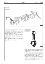
Page 156: ...APRIL 2004 OVERHAUL 8 156 N60 ENT M37 ...

Page 157: ...emove them Withdraw the pistons including the connecting rods from the top of the engine block Remove the screws 1 and the main bearing caps 2 The second last main bearing cap 1 and the relevant support are fitted with shoulder half bearing 2 Use tool 99360500 1 and hoist to remove the crankshaft 2 from the block Remove the main half bearings 1 Remove the screws 2 and remove the oil nozzles 3 Keep...

Page 158: ...med using the bore dial gauge 99395687 1 fitted with the dial gauge previously set to zero on the ring gauge 2 of the cylinder barrel diameter Measurements shall be performed on each cylinder at three different heights in the barrel and on two planes perpendicular with each other one parallel to the longitudinal axis of the engine A and the other perpendicular B Maximum wear is usually found on pl...

Page 159: ...rinding all barrels shall have the same oversize 0 5 mm Checking head supporting surface on cylinder unit Check main bearing housings as follows fit the main bearings caps on the supports without bearings tighten the fastening screws to the specified torque use the proper internal gauge to check whether the housing diameter is falling within the specified value Replace if higher value is found OVE...

Page 160: ...ot show seizing or wear Use bore dial gauge 3 to measure camshaft front and rear bush 2 and intermediate housing 1 diameter Measurements shall be performed on two perpendicular axes BUSHES Checking cam lift and pin alignment Set the camshaft on the tailstock and using a 1 100 gauge set on the central support check whether the alignment error is not exceeding 0 04 mm otherwise replace the camshaft ...

Page 161: ...70173 Figure 16 CAMSHAFT BUSH AND HOUSING MAIN DATA Value to be obtained after driving the bushes Sec A A OVERHAUL APRIL 2004 N60 ENT M37 8 161 ...

Page 162: ...ubricate the camshaft bushes and fit the camshaft 1 taking care not to damage the bushes or the housings Set camshaft 3 retaining plate 1 with the slot facing the top of the engine block and the marking facing the operator then tighten the screws 2 to the specified torque Bush replacement Fitting tappets camshaft When refitting the bushes 1 direct them to make the lubricating holes 2 coincide with...

Page 163: ... decide the final diameter to which the pins are to be ground It is recommended to insert the found values in the proper table See Figure 26 Undersize classes are Journals and crankpins shall always be ground to the same undersize class Journals and crankpins undersize shall be marked on the side of the crank arm No 1 For undersized crankpins letter M For undersized journals letter B For undersize...

Page 164: ...APRIL 2004 OVERHAUL 8 164 N60 ENT M37 ...

Page 165: ...AFT JOURNAL AND CRANKPIN MEASURED VALUES Rated value Figure 29 MAIN OUTPUT SHAFT TOLERANCES Measured on a radius greater than 45 5 mm 0 500 between adjacent main journals 70577 Measuring journals and crankpins OVERHAUL APRIL 2004 N60 ENT M37 8 165 ...

Page 166: ...CE CHARACTERISTIC GRAPHIC SYMBOL SHAPE Roundness SHAPE Cilindricity Parallelism DIRECTION Verticality Straightness POSITION Concentricity or coaxiality Circular oscillation OSCILLATION Total oscillation Taper LEVELS OF IMPORTANCE FOR PRODUCT CHARACTERISTICS GRAPHIC SYMBOL CRITICAL IMPORTANT SECONDARY APRIL 2004 OVERHAUL 8 166 N60 ENT M37 ...

Page 167: ...e internal diameter Clean accurately the main half bearings 1 having the lubricating hole and fit them into their housings The second last main half bearing 1 is fitted with shoulder half rings Check that gear toothing 1 is not damaged or worn otherwise remove it using the proper puller 3 When fitting the new gear heat it to 180 C for 10 minutes in an oven and then key it to the crankshaft Finding...

Page 168: ...and the pins is found by comparing the width of the calibrated wire 2 at the narrowest point with the scale on the envelope 1 containing the calibrated wire The numbers on the scale indicate the backlash in mm Replace the half bearings and repeat the check if a different backlash value is found Once the specified backlash is obtained lubricate the main bearings and fit the supports by tightening t...

Page 169: ...2 measure the diameter of the piston 1 to determine the assembly clearance The clearance between the piston and the cylinder barrel can be checked also with a feeler gauge 1 as shown in thefigure The diameter shall be measured at 12 mm from the piston skirt MAIN DATA CONCERNING KS PISTON PINS AND SPLIT RINGS Value measured on 99 mm diameter 2 Pistons Measuring piston diameter OVERHAUL APRIL 2004 N...

Page 170: ...een the sealing rings 3 of the 2nd and 3rd slot and the relevant housings on the piston 2 using a feeler gauge 1 DIAGRAM FOR MEASURING THE CLEARANCE X BETWEEN THE FIRST PISTON SLOT AND THE TRAPEZOIDAL RING Since the first sealing ring section is trapezoidal the clearance between the slot and the ring shall be measured as follows make the piston 1 protrude from the engine block so that the ring 2 p...

Page 171: ...tain the specified diameter Connecting rods Every connecting rod is marked as follows On body and cap with a number showing their coupling and the corresponding cylinder In case of replacement it is therefore necessary to mark the new connecting rod with the same numbers of the replaced one On body with a letter showing the weight of the connecting rod assembled at production S V 1820 to 1860 yell...

Page 172: ...onnecting rod 5 bending by comparing two points C and D of the pin 3 on the vertical plane of the connecting rod axis Position the vertical support 1 of the dial gauge 2 to rest the latter on pin 3 point C Move the connecting rod forwards and backwards to find pin top position then in this condition reset the dial gauge 2 Move the spindle with the connecting rod 5 and repeat the check of the top p...

Page 173: ...g TOP facing upwards and their openings shall be displaced with each other by 120 Fit half bearings 1 on connecting rod and cap Lubricate accurately the pistons including the split rings and the cylinder barrel inside Use band 99360605 2 to fit the connecting rod piston assembly 1 into the cylinder barrels and check thefollowing the number of each connecting rod shall correspond to the cap couplin...

Page 174: ...o the oil nozzle position Finding crankpin clearance To measure the clearance proceed as follows clean the parts accurately and remove any trace of oil set a piece of calibrated wire 2 on the output shaft pins 1 fit the connecting rod caps 3 with the relevant half bearings 4 Lubricate the screws 1 with engine oil and then tighten them to the specified torque using the torque wrench 2 Apply tool 99...

Page 175: ...ted with base 99370415 2 to check piston 3 protrusion at T D C with respect to the top of the engine block Protrusion shall be 0 28 to 0 52 mm Before the final fitting of the connecting rod cap fastening screws check that their diameter measured at the centre of the thread length is not 0 1 mm than the diameter measured at approx 10 mm from screw end Check manually that the connecting rods 1 are s...

Page 176: ...ER HEAD Removing the valves Valve removal shall be performed using tool 99360268 1 and pressing the cap 3 so that when compressing the springs 4 the cotters 2 can be removed Then remove the cap 3 and the springs 4 Repeat this operation for all the valves Overturn the cylinder head and withdraw the valves 5 70321 70322 Figure 70 Figure 71 Sealing rings 1 for intake valves are yellow Sealing rings 2...

Page 177: ... plug surfaces with water repellent sealant Checking cylinder head supporting surface Distortion found along the whole cylinder head shall not exceed 0 20 mm If higher values are found grind the cylinder head according to values and indications shown in the following figure 70325 Figure 73 The rated thickness A for the cylinder head is 105 0 25 mm max metal removal shall not exceed thickness B by ...

Page 178: ...18 and removing as less material as possible Check the valve stem 1 using a micrometer 2 it shall be 6 970 6 999 Use a magnetic base dial gauge 1 set as shown in the figure the assembling clearance shall be 0 052 0 092 mm Turn the valve 2 and check that the centering error is not exceeding 0 03 mm Removing carbon deposits checking and grinding valves Checking clearance between valve stem and valve...

Page 179: ...e shall comply with the value shown in the figure Check the valve seats 2 If slight scoring or burnout is found regrind seats using tool 99305018 1 according to the angle values shown in Figure 80 VALVE SEATS Regrinding replacing the valve seats VALVE SEATS MAIN DATA INTAKE Figure 80 VALVE GUIDE OVERHAUL APRIL 2004 N60 ENT M37 8 179 ...

Page 180: ...amage the cylinder head until they can be extracted from the cylinder head using a punch Heat the cylinder head to 80 100 C and using the proper punch fit the new valve seats previously cooled into the cylinder head Use tool 99305018 to regrind the valve seats according to the values shown in Figure 80 MAIN DATA CONCERNING THE SEATS ON THE CYLINDER HEAD EXHAUST INTAKE APRIL 2004 OVERHAUL 8 180 N60...

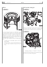
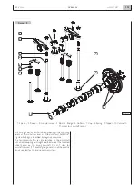
Page 181: ...OVERHAUL APRIL 2004 N60 ENT M37 8 181 ...

Page 182: ...e guides according to the position marked at removal Fit the sealing rings 2 and 3 on the valve guide Position on the cylinder head the spring 4 the upper cap 3 use tool 99360268 1 to compress the spring 4 and lock the parts to the valve 5 by the cotters 2 Sealing rings 2 for intake valves are yellow and sealing rings 3 for exhaust valves are green VALVE SPRINGS 70333 Figure 88 After regrinding ch...

Page 183: ...ead gasket 1 with the marking TOP 1 facing the head The arrow shows the point where the gasketthickness isgiven 70335 Figure 89 Refitting the cylinder head Before re utilising the fixing screws for the cylinder head verify there is no evidence of wear or deformation and in that case replace them OVERHAUL APRIL 2004 N60 ENT M37 8 183 ...

Page 184: ...acket 43 6 4 3 0 6 M10 x 80 Screw fixing pump water inlet pipe and support bracket 43 6 4 3 0 6 M10 x 30 Screw fixing the electric engine starter 43 6 4 3 0 6 M12 x 30 Screw fixing the sea water pump 85 8 8 5 0 8 M10 x 120 Screw for lower anchoring of the exhaust manifold 53 6 5 3 0 6 M10 x 150 Screw for lower anchoring of the exhaust manifold 53 6 5 3 0 6 N60 ENT M37 OVERHAUL 8 184 APRIL 2004 CHA...

Page 185: ...se 1 60 5 6 0 5 Phase 2 60 5 M10 Screw fixing crankcase base plate 43 5 4 3 0 4 M18 Nut to secure high pressure pump gear 105 5 10 5 0 5 M8 Nuts fixing fuel pump 24 4 2 4 0 4 1 2 inch plug on the cylinder head 24 4 2 4 0 4 1 4 inch plug on the cylinder head 36 5 3 6 0 5 3 4 inch plug on the cylinder head 12 2 1 2 0 2 M6 Screws fixing injectors 8 5 0 8 0 85 0 08 Nut fixing union to supply injector ...

Page 186: ...engine coolant inlet connection 43 6 4 3 0 6 Fixing bend 90 if necessary on engine fluid inlet connection 24 4 2 4 0 4 M6 Screw fixing engine coolant outlet union 10 2 1 0 2 Fixing pins on crankcase for exhaust manifold 10 2 1 0 2 M12 Screw fixing damper adapter Phase 1 50 5 5 0 5 and damper on crankshaft Phase 2 90 M10 Screw fixing pulley on crankshaft 68 7 6 8 0 7 M8 Screw fixing water pump 24 4...

Page 187: ...5 5 3 5 0 5 Oil pipe fixing on adapter M10 for turbine lubrication to crankcase 43 6 4 3 0 6 M8 oil drain pipe fixing on turbine 24 4 2 4 0 4 M6 Fixing for oil return from the cylinder head to the flywheel box 10 2 1 0 2 M12 Screw fixing engine flywheel Phase 1 30 4 3 0 4 Phase 2 60 5 M8 Screw fixing front bracket for lifting engine 24 4 2 4 0 4 Screw fixing engine oil sump 24 4 2 4 0 4 N60 ENT M3...

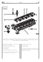
Page 188: ...N60 ENT M37 OVERHAUL 8 188 APRIL 2004 ...

Page 189: ...AFETY PRESCRIPTIONS Page SAFETY PRESCRIPTIONS 191 Standard safety prescriptions 191 Prevention of injury 191 During maintenance 191 Respect of the Environment 192 N60 ENT M37 SAFETY PRESCRIPTIONS 9 189 APRIL 2004 ...

Page 190: ...N60 ENT M37 SAFETY PRESCRIPTIONS 9 190 APRIL 2004 ...

Page 191: ... anti fire specially provided containers Do not execute any intervention if not provided with necessary instructions Do not use any tool or equipment for any different operation from the ones they ve been designed and provided for serious injury may occur In case of test or calibration operations requiring engine running ensure that the area is sufficiently aerated or uti lize specific vacuum equi...

Page 192: ...ration of electronic components shall totally compromise engine assistance warranty and furthermore may affect engine correct working and duration Respect of the Environment Respect of the Environment shall be of primary impor tance all necessary precautions to ensure personnel s safety and health shall be adopted Be informed and inform the personnel as well of laws in force regulating use and exh...

Page 193: ......

Page 194: ...IVECO S p A PowerTrain Viale Dell Industria 15 17 20010 Pregnana Milanese MI Italy Tel 39 02 93 51 01 Fax 39 02 93 59 00 29 www ivecomotors com ...

Reviews: