


The successful outcome of repair work is assured by the
operator’s experience and ability and by compliance with the
following instructions.
Before performing work involving components of the injec-
tion system, take note of the content of the ECU fault mem-
ory with the appropriate IVECO MOTORS diagnosing
equipment, writing the results down or printing them.
❏
Replacement of the ECU EDC 7 must be authorized by
IVECO MOTORS after specific agreements with the
Technical Assistance Service.
❏
The electro-injectors cannot be overhaul; their replace-
ment must be authorized by IVECO MOTORS with the
specific agreement of the Technical Assistance Service;
for disassembly, follow the indications provided in the
specific paragraph of this Section.
❏
Keep parts and components clean, making sure that dur-
ing handling and assembly (starting with the simple
replacement of filter and pre-filter) no sludge or foreign
matter is allowed to enter the lines, with particular
attention to the fuel supply line in the segment down-
stream of the filter.
❏
Maintain the proper polarization of all electrical con-
nections.
❏
Tighten the threaded connections to the prescribed
torque.
❏
Ensure that the flywheel and camshaft sensors are posi-
tioned so they abut, ensuring they are as close to per-
pendicular as possible with the bearing surface.
CAUTION
❏
Do not disconnect electrical connections without
removing power from the circuits first.
❏
Do not proceed with operating simulations with
unsuitable tools and instruments.
❏
Do not force measuring probes or mechanical tools
into the electrical connections.
❏
Do not proceed with arc welding without first discon-
necting electronic system units.
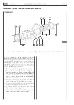
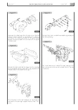
To proceed with the overhaul of the engine or its parts, you
must disconnect the electrical connections of the injection
system’s components and of the sensors providing indica-
tions on the control panel.
To proceed as indicated, we provide below the procedure to
avoid the risk that the ECU of the injection system may
detect and store errors or system faults.
❏
Set the key switch to the STOP position
❏
Wait 10 sec. and disconnect the battery terminals
❏
Disconnect the connections according to the prescrip-
tions set out in Section 3
❏
Remove, if necessary, the entire wiring harness from the
retaining bracket.
❏
Remove, if necessary, the complete electronic unit after
disconnecting the multipolar connectors.
N60 ENT M37
SERVICING OPERATIONS ON INSTALLED ENGINE
6.126
APRIL 2004
PRESCRIPTIONS FOR WORK ON THE INJECTION SYSTEM AND ITS COMPONENTS
Summary of Contents for N60 ENT M37
Page 4: ...N60 ENT M37 IV APRIL 2004 ...
Page 52: ...N60 ENT M37 OVERVIEW 1 52 APRIL 2004 ...
Page 54: ...N60 ENT M37 TECHNICAL DATA 2 54 APRIL 2004 ...
Page 60: ...N60 ENT M37 TECHNICAL DATA 2 60 APRIL 2004 ...
Page 62: ...N60 ENT M37 ELECTRICAL EQUIPMENT 3 62 APRIL 2004 ...
Page 92: ...N60 ENT M37 DIAGNOSTICS 4 92 APRIL 2004 ...
Page 116: ...N60 ENT M37 DIAGNOSTICS 4 116 APRIL 2004 ...
Page 118: ...N60 ENT M37 MAINTENANCE 5 118 APRIL 2004 ...
Page 122: ...N60 ENT M37 MAINTENANCE 5 122 APRIL 2004 ...
Page 124: ...N60 ENT M37 SERVICING OPERATIONS ON INSTALLED ENGINE 6 124 APRIL 2004 ...
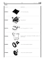
Page 139: ...SECTION 7 TOOLS Page TOOLS 141 N60 ENT M37 TOOLS 7 139 APRIL 2004 ...
Page 140: ...N60 ENT M37 TOOLS 7 140 APRIL 2004 ...
Page 146: ...N60 ENT M37 TOOLS 7 146 APRIL 2004 ...
Page 156: ...APRIL 2004 OVERHAUL 8 156 N60 ENT M37 ...
Page 164: ...APRIL 2004 OVERHAUL 8 164 N60 ENT M37 ...
Page 181: ...OVERHAUL APRIL 2004 N60 ENT M37 8 181 ...
Page 188: ...N60 ENT M37 OVERHAUL 8 188 APRIL 2004 ...
Page 190: ...N60 ENT M37 SAFETY PRESCRIPTIONS 9 190 APRIL 2004 ...
Page 193: ......


