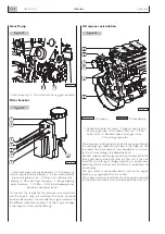


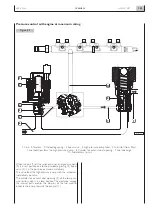


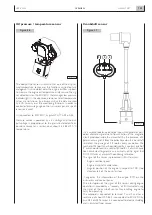
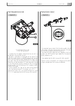


The internal volume of the rail is sized in such a way as to
allow a fast pressurization during transient states and at the
same time to level pressure surging caused by the openings
and the closures of the injectors and by the cyclic operation
of the high pressure pump. This function is facilitated by the
gauge hole located after the high pressure pump. At the ends
of the rail the internal pressure sensor and overpressure
valve are located. Every piping connected to the rail under-
go pressure above 1600 bar, and for this reason the piping
disassembled have to be replaced. In the case of mainte-
nance actions on the high pressure line, special care is to be
given to avoid the introduction of dirt.
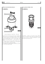
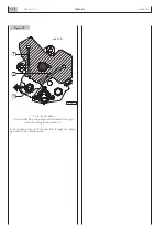
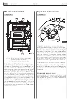
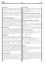
Two stage overpressure valve
Fitted on one end of the rail, it protects the system compo-
nents in case of malfunction of the rail pressure sensor or of
the pump pressure control causes and excessive pressure
increase in the high pressure system.
It is of a mechanical type and it has a double operating
threshold: 1750 bar and 800 bar.
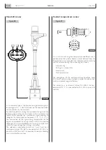
In the case in the high pressure system 1750 bar is reached
the valve comes into action initially as a normal one stage
to let the fuel backflow and thus consequently reducing
pressure to safety values and afterwards mechanically con-
trols the pressure in the rail up to about 800.The two stage
valve can be recognized by the acronym F775 inside the
encoding.
This valve allows to operate the engine for prolonged times
under limited performance and avoids the excessive over-
heating of the fuel preserving the system components
N60 ENT M37
OVERVIEW
1.39
APRIL 2004
04_053_N
1
2
4
3
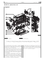
Figure 48
Figure 49
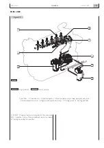
04_054_N
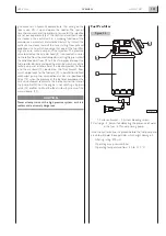
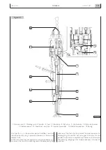
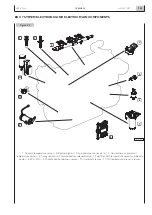
Rail and high pressure piping
1. Pressure sensor - 2. Fuel inlet from the high pressure pump - 3. Common Rail - 4. Overpressure valve.
Summary of Contents for N60 ENT M37
Page 4: ...N60 ENT M37 IV APRIL 2004 ...
Page 52: ...N60 ENT M37 OVERVIEW 1 52 APRIL 2004 ...
Page 54: ...N60 ENT M37 TECHNICAL DATA 2 54 APRIL 2004 ...
Page 60: ...N60 ENT M37 TECHNICAL DATA 2 60 APRIL 2004 ...
Page 62: ...N60 ENT M37 ELECTRICAL EQUIPMENT 3 62 APRIL 2004 ...
Page 92: ...N60 ENT M37 DIAGNOSTICS 4 92 APRIL 2004 ...
Page 116: ...N60 ENT M37 DIAGNOSTICS 4 116 APRIL 2004 ...
Page 118: ...N60 ENT M37 MAINTENANCE 5 118 APRIL 2004 ...
Page 122: ...N60 ENT M37 MAINTENANCE 5 122 APRIL 2004 ...
Page 124: ...N60 ENT M37 SERVICING OPERATIONS ON INSTALLED ENGINE 6 124 APRIL 2004 ...
Page 139: ...SECTION 7 TOOLS Page TOOLS 141 N60 ENT M37 TOOLS 7 139 APRIL 2004 ...
Page 140: ...N60 ENT M37 TOOLS 7 140 APRIL 2004 ...
Page 146: ...N60 ENT M37 TOOLS 7 146 APRIL 2004 ...
Page 156: ...APRIL 2004 OVERHAUL 8 156 N60 ENT M37 ...
Page 164: ...APRIL 2004 OVERHAUL 8 164 N60 ENT M37 ...
Page 181: ...OVERHAUL APRIL 2004 N60 ENT M37 8 181 ...
Page 188: ...N60 ENT M37 OVERHAUL 8 188 APRIL 2004 ...
Page 190: ...N60 ENT M37 SAFETY PRESCRIPTIONS 9 190 APRIL 2004 ...
Page 193: ......


