- 16 -
(4)
A pressure gauge must be
attached on the discharge
piping to ease the pressure
setting of the relief valve.
This attachment also helps in
the early detection of pump
abnormality.
(5)
For connection, use a thick
hose which can withstand
pump pressure. Since the
hose on the suction side, in
particular, tends to be crushed
by sucking force, the use of
a Teflon
®
hose or something
similar is recommended.
(When handling hot liquid,
special care should be taken.)
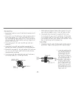
Discharge valve
Pressure gauge
10-2. Piping
(1)
In order to reduce the friction
resistance of liquid, the piping
should be as short and with as
few bends as possible.
(2)
The inlet and outlet joints
of the pump should be com-
pletely sealed with sealing
tape, etc., to prevent them
from sucking air. If the
sealing is incomplete on the
suction side, in particular, air
is sucked in and the perfor-
mance of the pump is low-
ered.
Joint size
Refer to "Identification
Code."
(3)
When screwing the joint to
the pump, hold the pump
body rather than the motor by
hand, to avoid applying exces-
sive force on the motor and
pump attachment section. For
screwing the joint, the fasten-
ing torque shall be 0.49 N
•
m
or lower.


