- 24 -
<Disassembling>
1.
Remove the 3 machine screws (33) and detach the pump unit off
the motor (1).
2.
Remove the screw (32)with, spring washer , and plate washer to
detach the pump head (17). In the case of MDG-R2( )V type,
never disassemble the adjusting screw (25), O ring (24), nut (28),
and plain washer (29). Touching these parts may change the set
pressure of the relief valve.
3.
Remove the gasket A (18), relief valve (26), and relief valve
spring (27).
4.
Remove the 3 screws(34) and detach the mounting plate (7),
packing B (20), bracket (8), and gasket B (19) off the pump unit.
5.
Remove the rear casing (5). Leave the packing C (21) on the rear
case as it is. In this step, be careful with the liquid which may
remain inside the rear casing.
6.
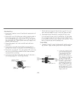
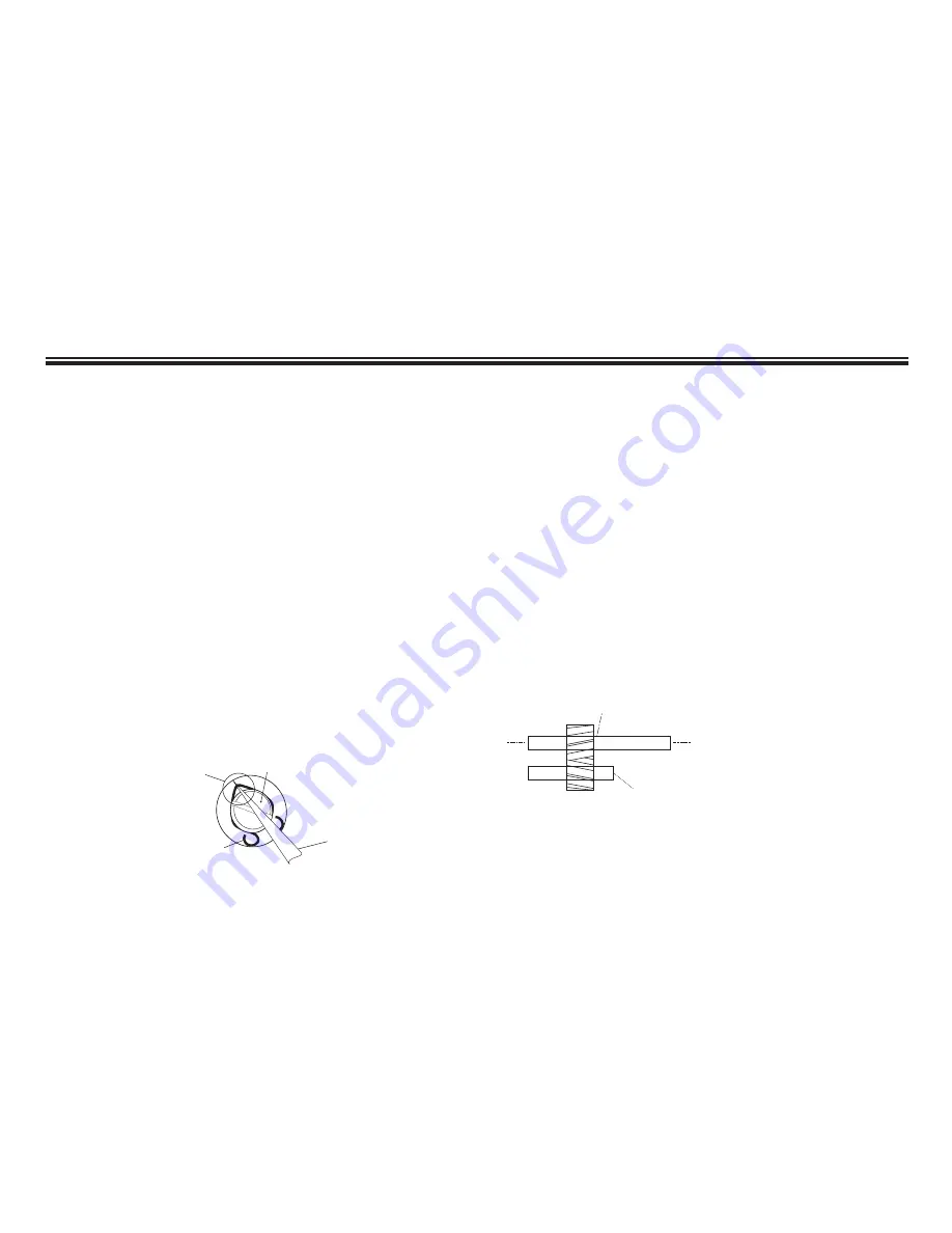
Use tweezers or the like to detach the stop ring (2) and remove
the retaining spring (22). (See the figure below)
7.
Detach the driven magnet (6) from the drive gear (9). Store the
removed driven magnet in a place free of steel powder or dust.
8.
Disassemble the rear bearing (14), rear plate (16), drive gear
(9), driven gear (10), gear case (11), parallel pins (12), front plate
(15), and front bearing (13) in the order described. Handle these
parts carefully so as not to cause scratches on the surfaces. Store
them in a dust-free place after cleaning them.
<Assembling>
1.
Attach the O ring (23) to the front bearing (13) and the rear bear-
ing (14) each. Apply silicone grease to the O ring beforehand.
Tweezers
Magnet
retainer ring
Driving gear
Hooked on magnet
retainer ring
Drive gear (9)
Driven gear (10)
Rear
bearing
side
Front
bearing
side
2.
Attach the parallel pins (12)
onto the front bearing (13).
Then, assemble the front
plate (15), gear case (11),
drive gear (9), driven gear
(10), rear plate (16), and rear
bearing (14) in the order
described. In this step, be
careful to match the hole
positions of the respective
parts. In addition, be sure
to insert the drive gear (9)
and the driven gear (10) in
the directions shown in the
figure on the left.


