REL 1.2
Page 54 of 82
i.MX6 Qseven PMIC SOM Hardware User Guide
iWave Systems Technologies Pvt. Ltd.
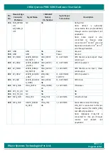
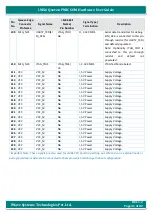
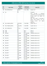
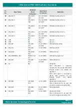
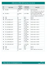
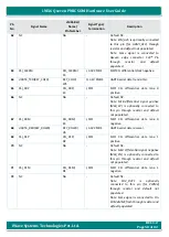
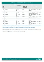
Table 7: Expansion Connector2 Pin Assignment
Pin
No
Signal Name
i.MX6 Ball
Name/
Pin Number
Signal Type/
Termination
Description
1
MLBDAT(GPIO_2)
GPIO_2/
T1
IO,3.3V CMOS
MLB single ended data.
Note: MLB differential data negative
(MLB_DN) is optionally connected to
this pin through resistor and default
not populated.
2
MLBCLK(GPIO_3)
GPIO_3/
R7
I,3.3V CMOS
MLB single ended clock.
Note: Optionally same signal
is
connected to Expansion connector1
10
th
pin (for ESAI_HCKR) through
resistor and default not populated.
Note: MLB differential clock positive
(MLB_CP) is optionally connected to
this pin through resistor and default
not populated.
3
NC
NA
-
Default NC.
Note: MLB differential data positive
(MLB_DP) is optionally connected to
this pin through resistor and default
not populated.
4
MLBSIG(GPIO_6)
GPIO_6/
T3
I, 3.3V CMOS
MLB single ended signal.
Note: MLB differential clock negative
(MLB_CN) is optionally connected to
this pin through resistor and default
not populated.
5
GND
NA
Power
Ground.
6
GND
NA
Power
Ground.
7
NC
NA
-
Default NC.
Note:
KEY_ROW1
is
optionally
connected to this pin (for KEY_ROW1)
through resistor and default not
populated.
Note: Same signal is connected to
Qseven edge connector 177
th
Pin
through
resistor
and
default
populated.
8
KEY_ROW5(CSI0_DAT5)
CSI0_DAT5/
P2
O, 3.3V CMOS
Keypad row 5.
9
KEY_ROW6(CSI0_DAT7)
CSI0_DAT7/
N3
O, 3.3V CMOS
Keypad row 6.

