REL1.2
Page 21 of 62
RZ/G1E SODIMM SOM Hardware User Guide
iWave Systems Technologies Pvt. Ltd.
2.7.5
SD Interface
The RZ/G1E SODIMM SOM supports one SD interface port on SODIMM Edge connector. RZ/G1E CPU’s SDHI0
controller is used for SD interface. It supports 1-bit or 4-bit transfer mode for SD memory/SDIO and works up to
SDR104 class transfer rate at max. 97.5 Mbytes/s @ 195 MHz. RZ/G1E CPU supports SDIO card detect function &
write protect function and are connected from SODIMM Edge connector.
The RZ/G1E SODIMM SOM supports configurable IO voltage levels for SDHI0 lines which can be controlled through
RZ/G1E GPIO GP0_20. If GP0_20 is set to low, then 1.8V IO level is selected for SDHI0 lines. If GP0_20 is set to high,
then 3.3V IO level is selected for SDHI0 lines.
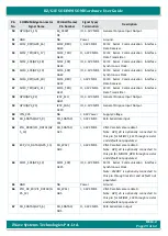
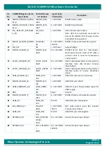
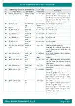
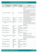
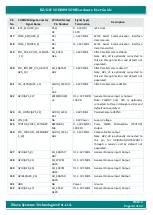
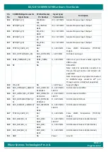
For more details, refer SODIMM Edge connector pins 82, 105, 107, 108, 109, 111, 112 & 114 on
2.7.6
Parallel Camera Interface
The RZ/G1E SODIMM SOM supports one parallel camera interface on SODIMM Edge Connector. RZ/G1E
CPU’s
VIN1
channel is used for this 8bit parallel camera interface.
The RZ/G1E
CPU’s
Video Input Module (VIN) is a video capture module that supports YCbCr-422 data through the
ITU-R BT.601, ITU-R BT.656 or ITU-R BT.709 interface and RGB data through the ITUR BT.601 or ITU-R BT.709
interface. The VIN supports Vertical and Horizontal Scaling where the image can be scaled up and down up to three
times in the vertical and two times in the horizontal directions. Also, it has two clipping circuits, which independently
handle images with up to 2048 × 2048 pixels. The VIN provides a colour space conversion function from YCbCr-422 to
RGB, a format conversion function from RGB to ARGB.
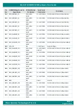
For more details, refer SODIMM Edge connector pins 62, 63, 66, 70, 93, 104, 110, 119, 120, 121, 123 &126 on
Note: In RZ/G1E CPU, EtherMAC and VIN1 are multiplexed in same pins and so either one interface only can be used
at a time. By default, VIN1 camera interface is supported in RZ/G1E SODIMM SOM. iWave also supports separate
RZ/G1E SODIMM SOM with EtherMAC support instead of VIN1.
Note: In RZ/G1E SODIMM SOM, VIN1 and MSIOF1 interface signals are connected to same pins of SODIMM Edge
connector (through isolating resistors) and so either one interface only can be used at a time. By default, VIN1
camera interface is supported on SODIMM Edge. In EtherMAC supported RZ/G1E SODIMM SOM, MSIOF1 (and some
extra GPIOs) is supported on SODIMM edge (instead of VIN1).
Summary of Contents for iW-RainboW-G22M
Page 49: ...REL1 2 Page 49 of 62 iWave Systems Technologies Pvt Ltd RZ G1E SODIMM SOM Hardware User Guide...
Page 50: ...REL1 2 Page 50 of 62 iWave Systems Technologies Pvt Ltd RZ G1E SODIMM SOM Hardware User Guide...
Page 51: ...REL1 2 Page 51 of 62 iWave Systems Technologies Pvt Ltd RZ G1E SODIMM SOM Hardware User Guide...
Page 62: ...REL1 2 Page 62 of 62 iWave Systems Technologies Pvt Ltd RZ G1E SODIMM SOM Hardware User Guide...


