REL1.1
Page 29 of 51
iWave Systems Technologies Pvt. Ltd.
RZ/G1C SBC Hardware User Guide
2.9.1
Data UART Interface
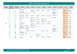
The RZ/G1C SBC supports one Data UART interface on Expansion connector1. RZ/G1C
CPU’s
SCIF2 controller is used
for Data UART interface with Transmit & Receive signal on Expansion connector1.
The RZ/G1C
CPU’s
SCIF module has two 16-stage FIFO buffers separately for transmission and reception, which
enables fast, efficient, and uninterrupted full duplex communication. It has On-chip baud rate generator that allows
any bit rate to be selected. Also it supports DMA transfers.
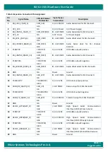
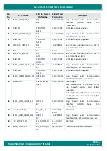
For more details, refer Expansion connector1 pins 8 & 10 for SCIF2 on
2.9.2
SPI Interface
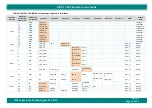
The RZ/G1C SBC supports one SPI interface on Expansion connector1. RZ/G1C
CPU’s MSIOF2 with
two chip select is
used for SPI interface which supports full-duplex synchronous four-wire serial interface with DMA.
The RZ/G1C
CPU’s MSIOF
2 controller supports serial formats IIS, SPI (master and slave modes) at max speed of
26Mbps. It supports 32bit x 64 stages for transmit FIFOs & 32bit × 256 stages for receive FIFOs and allows MSB first
or LSB first selectable for data transmission and reception.
For more details, refer Expansion connector1 pins 19, 21, 23, 24 & 26 pins for MSIOF2 on
2.9.3
I2C Interface
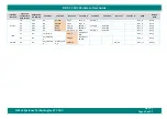
The RZ/G1C SBC supports two I2C interface on Expansion connector1
. RZ/G1C CPU’s I2C
1 & I2C4 channels are used
for I2C interface which is compatible with the standard NXP I2C bus protocol. It supports standard mode with data
transfer rates up to 100 kbps and Fast mode with data transfer rates up to 400 kbps. It also supports Master/slave
functions and Multi-master functions. RZ/G1C CPU I2C is not compliant with the 5V input.
For more details, refer Expansion Connector1 pins 27 & 28 for I2C1 and 3 & 5 for I2C4 on
Note: I2C4 interface signals are also connected to On-board HDMI Transmitter with I2C address 0x72.
2.9.4
GPIO Interface
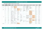
The RZ/G1C SBC supports many GPIOs (upto 17nos) on Expansion connector1.The RZ/G1C
CPU’s GPIO blocks provide
general-purpose pins that can be configured as either input or output. When configured as an output, it is possible
to write to an internal register to control the state driven on the output pin. When configured as an input, it is
possible to detect the state of the input by reading the state of an internal register. In addition, the GPIO input can
produce interrupt to the CPU core via the interrupt control block when corresponding registers are set.
For more details, refer Expansion Connector1 Pins 7, 11, 12, 13, 15, 16, 18, 22, 29, 31, 32, 33, 35, 36, 37, 38 & 40 for


