REL1.1
Page 34 of 51
iWave Systems Technologies Pvt. Ltd.
RZ/G1C SBC Hardware User Guide
2.10.4
Data UART Interface
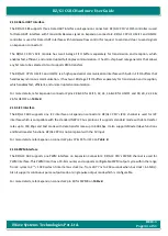
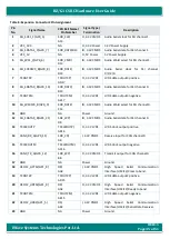
The RZ/G1C SBC supports three Data UART interface on Expansion connector2. RZ/G1C
CPU’s
SCIF5 controller is used
for Data UART interface with Transmit & Receive signal on Expansion connector2. RZ/G1C
CPU’s
HSCIF1 and HSCIF2
controller is used for Data UART interface with hardware flow control for request to send and clear to send signals
on Expansion connector2.
The RZ/G1C
CPU’s
SCIF module has two 16-stage FIFO buffers separately for transmission and reception, which
enables fast, efficient, and uninterrupted full duplex communication. It has On-chip baud rate generator that allows
any bit rate to be selected. Also it supports DMA transfers.
The RZ/G1C
CPU’s
HSCIF1 and HSCIF2 is a high speed serial communication interface with built-in FIFO buffers that
handles asynchronous communication. It has two 128-stage FIFO buffers separately for transmission and reception,
which enables fast, efficient, and uninterrupted communication.
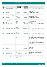
For more details, refer Expansion connector2 pins 28 & 30 for SCIF5, 32, 34, 36 & 38 for HSCIF1 and 18, 20, 22, 24 &
2.10.5
I2C Interface
The RZ/G1C SBC supports one I2C interface on
Expansion connector2. RZ/G1C CPU’s I2C3
channel is used for I2C
interface which is compatible with the standard NXP I2C bus protocol. It supports standard mode with data transfer
rates up to 100 kbps and Fast mode with data transfer rates up to 400 kbps. It also supports Master/slave functions
and Multi-master functions. RZ/G1C CPU is not compliant with the 5V input.
For more details, refer Expansion connector2 pins 37 & 39 for I2C3 on
2.10.6
PWM Interface
The RZ/G1C SBC supports one PWM interface on Expansion Connector2. RZ/G1C
CPU’s PWM0 channel is used for
PWM interface. This PWM timer has a 10-bit counter and supports configurable PWM output cycle within the range
from 2 cycles to 2
24
× 1024 cycles of internal bus clock (i.e. from 30.77 ns to 264 seconds when bus clock = 65 MHz).
Also it supports continuous pulse output mode or single pulse output mode which is configurable.
For more details, refer Expansion connector2 pin 40 for PWM0 on


