REL1.1
Page 37 of 51
iWave Systems Technologies Pvt. Ltd.
RZ/G1C SBC Hardware User Guide
2.11
Expansion Connector3 (20 Pin) Interfaces
The interfaces which are available at 20 Pin Expansion connector3 are explained in the following sections. This
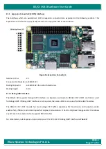
Expansion Connector3 (J7) is physically located at the top of the SBC as shown below.
Figure 16: Expansion Connector3
Number of Pins
- 20
Connector Part Number - 61302021121
Mating Connector
- 61302021821 from Wurth Electronics
Staking Height
- 6mm
2.11.1
Debug UART Interface
The RZ/G1C SBC supports Debug UART interfaces on Expansion connector3. RZ/G1
C CPU’s SCIF1 controller is used
for Debug UART. If Debug UART interface is not required, then same SCIF1 can be used for Data UART interface.
The RZ/G1C
CPU’s SCIF module has two 16
-stage FIFO buffers separately for transmission and reception, which
enables fast, efficient, and uninterrupted full duplex communication. It has On-chip baud rate generator that allows
any bit rate to be selected. Also it supports DMA transfers.
For more details, refer Expansion connector3 pins 17 & 19 for SCIF1 Debug UART interface on


