REL1.1
Page 38 of 51
iWave Systems Technologies Pvt. Ltd.
RZ/G1C SBC Hardware User Guide
2.11.2
Data UART/I2C Interface
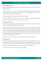
The RZ/G1C SBC supports one Data UART interfaces on Expansion connector3.
RZ/G1C CPU’s SCIF4 controller
is used
for Data UART interface.
The RZ/G1C
CPU’s SCIF module has
two 16-stage FIFO buffers separately for transmission and reception, which
enables fast, efficient, and uninterrupted full duplex communication. It has On-chip baud rate generator that allows
any bit rate to be selected. Also it supports DMA transfers.
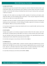
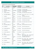
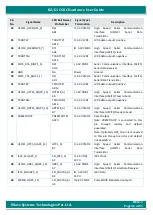
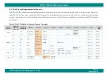
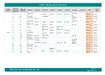
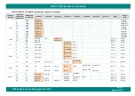
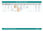
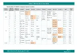
For more details, refer Expansion connector3 pins 18 & 20 for SCIF4 on
Note: If Data UART interface is not required on these pins, then the same pins can be configured as I2C0 interface.
Make sure to add the pullup resistors externally when these pins are used as I2C0.
2.11.3
Parallel Camera Interface
The RZ/G1C SBC supports one 8bit parallel camera interface. RZ/G1C CPU VIN0 channel is used for this 8bit parallel
camera interface and directly connected to Expansion Connector3.
The RZ/G1C
CPU’s
Video Input Module (VIN0) is a video capture module that supports YCbCr-422 data through the
ITU-R BT.601, ITU-R BT.656 or ITU-R BT.709 interface and RGB data through the ITUR BT.601 or ITU-R BT.709
interface. The VIN0 supports Vertical and Horizontal Scaling where the image can be scaled up and down up to three
times in the vertical and two times in the horizontal directions. Also, it has two clipping circuits, which independently
handle images with up to 2048 × 2048 pixels. The VIN provides a colour space conversion function from YCbCr-422 to
RGB, a format conversion function from RGB to ARGB.
For more details, refer Expansion connector3 pins 1,2,3,4,8,9,10,11,12,13,14 & 16 for VIN0 on
2.11.4
PWM Interface
The RZ/G1C SBC supports one PWM interface on Expansion Connector3. RZ/G1C
CPU’s PWM2 channel is used for
PWM interface. This PWM timer has a 10-bit counter and supports configurable PWM output cycle within the range
from 2 cycles to 2
24
× 1024 cycles of internal bus clock (i.e. from 30.77 ns to 264 seconds when bus clock = 65 MHz).
Also it supports continuous pulse output mode or single pulse output mode which is configurable.
For more details, refer Expansion connector3 pin 7 for PWM2 on


