REL0.1
Page 17 of 95
Kintex Ult FPGA SOM Hardware User Guide
iWave Systems Technologies Pvt. Ltd.
2.3.1.4
FPGA Configuration & Status
In Kintex Ult SOM, by default QSPI Flash is set as configuration device through mode pins. Memory configuration files are
generated from the BIT file in Vivado is programmed to QSPI through JTAG.
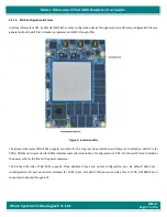
Figure 3: Indication LEDs
The Kintex Ult FPGA SOM supports two LEDs for the Program Done indication and Power LED indication. LED D2 is for
PROG_DONE and it is asserted for DONE indicates successful completion of configuration. LED D1 is for Power LED and it indicates
the power which is the final in the power sequence.
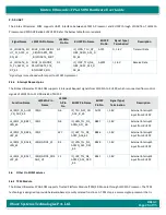
The Kintex Ult FPGA SOM supports three dedicated input and output configuration pins. By default, Weak pre -
reconfiguration I/O pull-up resistors disabled for PUDC_B pin, Standard FPGA power-on delay time for POR_OVERRIDE pin is
connected to Ground through 4.7K.


