16
Ena bled
1-2
*Defa ult
Disa bled
2-3
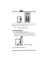
3.6.5 SCSI Terminator Control
JP1&JP2 a re both 3 pin jumper connectors. These a re for Low/ High Byte
SCSI Termina tor.
Function
JP1
Note
Low Byte SCSI Termina tor Alwa ys On
1-2
Low Byte SCSI Termina tor Alwa ys Off
off
Low Byte SCSI Termina tor Controlled by BIOS
2-3
*Defa ult
Function
JP2
Note
High Byte SCSI Termina tor Alwa ys On
1-2
*Defa ult
High Byte SCSI Termina tor Alwa ys Off
Off
High Byte SCSI Termina tor Controlled by BIOS
2-3
3.6.6 Wide SCSI Select
JP5 is a 2 pin jumper connector. This is for Wide SCSI function ena bled.
Function
JP5
Note
Wide SCSI Ena bled
On
*Defa ult
Wide SCSI Disa bled
Off
3.6.7 SCSI LED
J29 pin jumper connector. This is for SCSI LED.
Reference to Cha ptor
3.9 for more deta il.
3.7 Adaptec
RAIDport option
3.7.1 SCSI RAIDPort
Turn this SCSI embedded Motherboa rd to be ha rdwa re a ssist RAID rea dy
by a dding the RAIDBUS 1000 or the Ada ptec ARO 1130 a da pter.
This RAID port option by a dding the RAIDBUS 1000 a da pter ca n
support :
◼
Bus Ma ster DMA
◼
Up to 133 Mbyte/Sec Burst ra te
◼
RAID level :5,1,0 a nd 0/1
◼
Fully Netwa re 3.11, 3.12, 4.x & WinNT 3.51 supported by Ada ptec
The PCI solt #1 uses the 120 pin for PCI Loca l Bus with 60 pin RAID
Port option.
Summary of Contents for P55TU
Page 4: ......

