19
If you a re using the ordina ry pa ra llel ca bles running a t the EPP or ECP
mode tha t this controller provided, you ma y experience tha t the da ta
efforts.
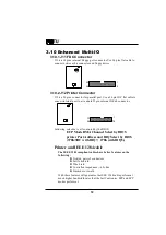
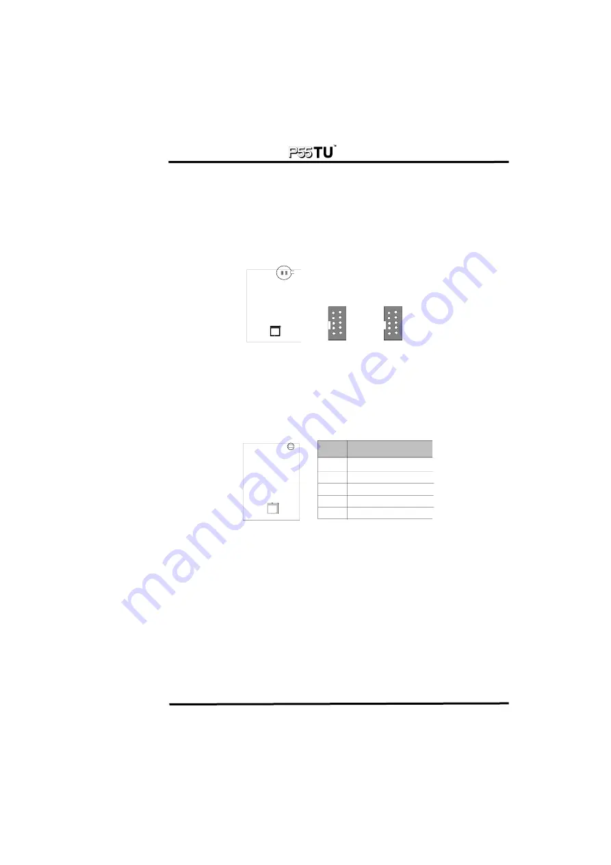
3.10.3 J14/J15 Serial Port
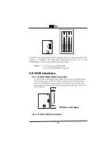
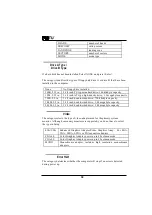
J14/J15 a re 10 pins interna l Seria l 1/Seria l 2 port connector. This system
boa rd provides two fla t ca ble to convert interna l Seria l ports to a
sta nda rd 9 a nd 25 pins externa l RS-232 port.
Serial 1
Serial 2
1
2
3
4
5
6
7
8
9
10
COM#A
COM#B
1
2
3
4
5
6
7
8
9
10
3.11 Others
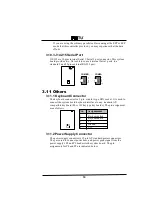
3.11.1 Keyboard Connector
The keyboa rd connector is a 5-pin, circula r-type DIN socket. It is used to
connect the system boa rd keyboa rd interfa ce to a ny sta ndard AT-
compa tible keyboa rd (84 or 101key type keyboa rds). The pin a ssignment
a re a s follows:
1
2
3
4
5
Keyboard clock
Keyboard data
n/c
Ground
VCC
Pin
Assignmemnt
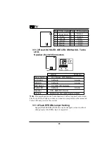
3.11.2 Power Supply Connector
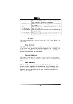
The power supply connector is 12-pin AT sta nda rd power connectors.
They a re used to connect power lines a nd power good signa l from the
power supply's P8 a nd P9 hea ders to the system boa rd. The pin
a ssignments for P8 a nd P9 a re indica ted below:
Summary of Contents for P55TU
Page 4: ......

