background image


48


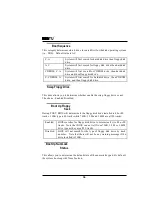
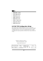
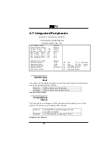
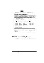
IRQ8 (RTC Alarm) 


IRQ9 (IRQ2 Redir) 


IRQ10 (Reserved) 


IRQ11 (Reserved) 


IRQ12 (Reserved) 


IRQ13 (Coprocessor) 


IRQ14 (Hard Disk) 


IRQ15 (Reserved) 


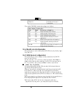
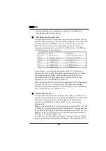
4.6 PnP/ PCI Configuration Setup 

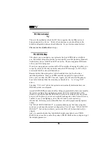
This section describes configuring  the PCI bus system.  PCI, or 

P

ersona l 

C

omputer 

I

nterconnect, is a  system which a llows I/O devices to opera te a t speeds 

nea ring the speed the CPU  itself uses when communica ting with its own specia l 
components.  This section covers some very technica l items a nd it is  strongly 
recommended tha t only experienced users should ma ke a ny cha nges to the defa ult 
settings. 


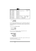
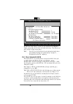
ROM PCI / ISA BIOS (2A59FI3D) 

   POWER  MANAGEMENT  SETUP 

       AWARD  SOFTWARE,  INC. 


Resources Controlled by 

: Manual 

PCI IRQ Actived By                      : Level          

Reset Configuration Date 

: Disabled 

PCI IDE IRQ Map To 

: PCI-AUTO 


 Primary        IDE       INT# 

: A 

IRQ-3    assigned  to 

: PCI/ISA PnP 

 Secondary    IDE       INT# 

: B 

Summary of Contents for P55TU

Page 1: ...ntent of Directive 89 336 ECC for Electromagnetic Compatibility Compliance was demonstrated to the following specifications as listed in the official Journal of the European Communities EN 50081 1 Emissions EN 55022 Radiated Class B EN 55022 Conducted Class B EN 60555 2 Power Harmonics EN 50082 1 Immunity IEC 801 2 Electrostatic Discharge IEC 801 3 RF Radiat IEC 801 4 Fast Transient ...

Page 2: ...on this SCSI Motherboard to outperform the whole system stability It equipe 4 of the 72 pin SIMM that supports EDO DRAM with ECC This manualis subject to change without notice This manualcontainsinformation protected by copyright law All rights are reserved No any part of this document may be used or reproduced in any forms or by any means or stored in a database orretrieval system without prior w...

Page 3: ... Chapter 4 Award BIOS Setup 4 1 Main Menu P26 4 2 Standard CMOS Setup P29 4 3 BIOS Features Setup P33 4 4 Chipset Feature Setup P39 4 5 Power Management Setup P46 4 6 PNP PCI Configuration P50 4 7 Integrated Peripherals P52 4 8 Load Setup Defaults P54 4 9 Supervisor User Password P54 4 10 IDE HDD Auto Detection P55 4 11 HDD Low Level Format P55 4 12 Save Exit Setup P55 4 13 Exit Without Saving P55...

Page 4: ......
Page 5: ...wer that could only be achieved by Mini computer Incorporatingthe new emerging industrial standard PeripheralComponent interconnect PCI Local Bus together with the standard 16 bit Industrial Standard Architecture ISA this SCSI Motherboard dramatically boots system I O through for even the most demandingapplication in today s market CPU CPU socket socket 7 supports the flexibility of different type...

Page 6: ...tware driver from Adaptec Inc include EZ SCSI for DOS Windows 7800 Family Set Driver for Netware Windows NT OS 2 SCO Unix Unixware IDE functions Built in dualPCI Bus EIDE Channels Support ATAPI AT Attachment Packet Interface USB interface Universal Serial Bus Plug and Play peripherals outside the box Up to 12Mbit Easy of use Floppy Interface Support both 3 1 2 and 5 1 4 floppy disk drives and Tape...

Page 7: ... to printer power on Others function Support both Fast Page DRAM or EDO DRAM SIMM Support Pentium CPU SMM System Management Mode Using Embeded Battery in RTC Real Time Clock which provides environmentalprotection and longer battery life 1 2 Specifications Physical Dimensions Length 330mm Width 220mm Environmental Requirements Temperature 0 55 degrees C operating or storage 5 to 95 non condensingre...

Page 8: ... Step 1 Install CPU and Cooler Make sure the Clock Frequency is set to the same as the CPU installed Choose the CPU speed by one jumperon JP10 Step 2 Install the memory Plug at least 2 PCS of 72 pins Micro Edge DRAM modules to either Bank0 or Bank1 Step 3 Install display controller and connect I O ports This system board is designed using PCI Peripheral Component Interconnect and ISA Industry Stan...

Page 9: ...tup data to the CMOS Exit the Setup Menu screen and then write to CMOS RAM And enjoy the high performance system board Step 8 After boot yoursystem O S insert the Adaptec EZ SCSI Installation diskette in a floppy disk drive and follow the EZ SCSI operation manualorreference to Adaptec 7800 Family Set manualwhich will guide you to install theDOS Windows Netware Windows NT OS 2 SCO UNIX Unixware CHA...

Page 10: ...wrench You should find the Following components when open the box 1 P55TU SCSI Motherboard 2 This Operation Manual 3 Adaptec software driver Diskette EZ SCSI 4 Adaptec 7800 Family ManagerSet software driver Diskettes 5 Adaptec EZ SCSI Manual 6 Adaptec 7800 Family ManagerSet Manual 7 68 pins high density internal Wide SCSI signal flat cable 8 50 pins internal SCSI signal flat cable 9 40 pins intern...

Page 11: ...7 3 2 Placement Placement Connector J3 1 J1 P55TU Keyboard PS2 mouse ISA Bank 0 Bank 1 CPU FAN Speaker Keylock Reset SW SCSI LED IDE LED SMI SW Turbo LED 1 ...

Page 12: ...8 Jumper J3 1 P55TU 1 2 50 V 2 70 V 2 83 V 3 38 V 3 52 V 75 90 100 120 133 150 166 180 200 MHz JP5 JP11 JP12 1 JP7 1 JP3 1 JP2 JP1 ...

Page 13: ...e of this 321 Pin ZIF socket up carefully and insert the CPU into ZIF socket And make sure the CPU Pin 1 is with the square base and it goes to particular hole on the ZIF socket Once you match the hole with Pin 1 then gently insert the CPU and press socket handle down 1 3 3 2 J22 CPU Cooler Fan Power Connector Warning Warning Warning CPU Cooler is required to be placed on top of the CPU all the ti...

Page 14: ... the jumpercap into the CPU clock that you desire The JP10 is a 2 X 9 pin jumper with one colored jumpercap on it One and only one jumpercap Expect when you use the Cyrix 120 CPU need to put on this connectorfor selecting the CPU clock Simply place the colored yellow jumpercap to the speed of the CPU really is the CPU internal externalclock ratio and ISA clock will be automatically selected by set...

Page 15: ... 166MHz If you are using Cyrix 6X86 CPU please be noted on Cyrix 6X86 120 which is 100 MHz CPU Both jumpers caps on 75 MHz and 100 MHz need to be placed To use other Cyrix CPU speed please refernce following table JP10 75 90 100 120 133 150 166 180 200 MHz Cyrix 120 JP10 75 90 100 120 133 150 166 180 200 MHz Cyrix 150 JP10 75 90 100 120 133 150 166 180 200 MHz Cyrix 166 Cyrix 120 100MHz Cyrix150 1...

Page 16: ...oltage 3 52V VRE is design when Cyrix CPU is installed 3 38V Default is for all the Intel P54C CPU 2 83V is reserve for the Intel P55C 2 7V and 2 5V is reserve for Cyrix M2 CPU 3 3 5 P54C P55C Select JP4 CPU JP4 Note P54C P54CS P54CT 1 2 1 2 Default P55C 2 3 2 3 3 4 Cache Memory The cache memory support for pipilined burst SRAM this will perform at least 10 fasterthan traditionalasynchronous SRAM ...

Page 17: ... DRAM 2 The 60 ns EDO DRAM is required 3 6 SCSI Interface 3 6 1 J3 Ultra Wide SCSI Connector J3 is a 68 pins 16 bit internal Ultra Wide SCSI connector It attaches the SCSI cable s from the P55TU SCSI controller to the SCSI peripherals The externalSCSI port expansion kit is a optionalfor your connecting externaldevices Be sure the cable s colored side should align to pin 1 of this connector Ultra S...

Page 18: ...le must run sequentially from one device to the next with no branches P55TU Ultral SCSI devices Ultra Wide SCSI devices Host ID7 50pin flat SCSI cable Internal SCSI Connection 68pin flat SCSI cable Note The 50 pin SCSI is an 8 bit SCSI bus the 68 pin SCSI is a 16 bit SCSI bus which hasa pin to pin connected to the 50 pins SCSI connector Note The SCSI termination must be onfor the both side The beg...

Page 19: ...ference to Chapter5 SCSI Select Utility for software setup 3 6 3 Set SCSI IDs You must assign a different SCSI ID to each device on the SCSI bus connected to the P55TU system board See yourSCSI device documentation fordirections on how to determine the ID and change it Ultra Ultra Wide SCSI devices that connect to this mainboard s SCSI connectorcan be assigned ID from 0 to 15 for 68 pin Wide SCSI ...

Page 20: ... 2 pin jumper connector This is for Wide SCSI function enabled Function JP5 Note Wide SCSI Enabled On Default Wide SCSI Disabled Off 3 6 7 SCSI LED J29 pin jumperconnector This is for SCSI LED Reference to Chaptor 3 9 for more detail 3 7 Adaptec RAIDport option 3 7 1 SCSI RAIDPort Turn this SCSI embedded Motherboard to be hardware assist RAID ready by addingthe RAIDBUS 1000 or the Adaptec ARO 1130...

Page 21: ...secondary IDE channel like CD ROM Each IDE connectorcan connect fortwo IDE devices and do not forget to set the first IDE device to Master and second IDE device to Slave when you connect two IDE devices in one connector P R I M A R Y I D E S E C O N D A R Y I D E P R I M A R Y I D E S E C O N D A R Y I D E 1 2 1 2 39 40 39 40 3 8 2 IDE LED J26 pins LED connector Reference to Chaptor3 9 for more de...

Page 22: ...b connector P R I N T 1 14 13 26 Following selection is all controled by the BIOS ECP Mode DMA Channel Select by BIOS printer Port Address and IRQ Select by BIOS 378h 3BC with IRQ7 278h with IRQ5 Printer and IEEE 1284 cable The IEEE 1284 compliant cables have better features on the following Twisted pairs of conductors Full foil shield Wire braid Controlled impedance 62 ohm Limited cross walk With...

Page 23: ...B 1 2 3 4 5 6 7 8 9 10 3 11 Others 3 11 1 Keyboard Connector The keyboard connectoris a 5 pin circular type DIN socket It is used to connect the system board keyboard interface to any standard AT compatible keyboard 84 or 101key type keyboards The pin assignment are asfollows 1 2 3 4 5 Keyboard clock Keyboard data n c Ground VCC Pin Assignmemnt 3 11 2 Power Supply Connector The power supply connec...

Page 24: ...eset Switch SCSI LED IDE LED SMI Switch Speaker Keylock On Reset Off Normal VCC GND NC Sound LED Anode NC GND Keylock GND On SMI Off Normale Turbo LED Right pin Left pin Cathode Anode Cathode Anode Cathode Anode Note This mainbaord has no Turbo function it will not support Turbo switch The Turbo LED will light on when you connect a computercase that mounted Turbo LED and power on this system 3 11 ...

Page 25: ...support 29xxx Default 2 3 12V Flash EPROM support 28xxx 3 11 5 PS 2 Mouse J22 1 1 Mouse data Red Mouse clock Biue Ground green NC Mouse VCC Yellow J10 is a 5 pin connector connect this port by a 1 x 5 IDC flat cable to a L frame mini din PS 2 mouse connector ...

Page 26: ... is then stored in battery backed RAM so that it retains the Setup information when the power is turned off The Award BIOS installed in yourcomputersystem ROM Read Only Memory is a custom version of an industry standard BIOS This means that it supports Intel Cyrix AMD processors in a standard IBM AT compatible input output system The BIOS provides critical low level support forstandard devices suc...

Page 27: ...ONTINUE DEL TO ENTER SETUP Using Setup In general you use the arrow keys to highlight items press Enter to select use the PageUp and PageDown keys to change entries press F1 for help and press Esc to quit The following table provides more detail about howto navigate in the Setup program using the keyboard Up arrow Move to previous item Down arrow Move to next item Left arrow Move to the item in th...

Page 28: ...gly recommend that you avoid makingany changes to the chipset defaults These defaults have been carefully chosen by both Award and your systems manufacturerto provide the absolute maximum performance and reliability Even a seemingly small change to the chipset setup has the potential for causing you to use the override A Final Note AboutSetup Not all systems have the same Setup While the basic loo...

Page 29: ...ion of each highlighted selection appears at the bottom of the screen Setup Items The main menu includes the following main setup categories Recall that some systems may not include all entries ROM PCI ISA BIOS 2A59F13D CMOS SETUP UTILITY AWARD SOFTWARE INC STANDARD CMOS PASSWORD SETTING BIOS FEATURES SETUP IDE HDD AUTO DETECTION CHIPSET FEATURES SETUP HDD LOWLEVEL FORMAT POWER MANAGEMENTSETUP SAV...

Page 30: ... access to the system and Setup or just to Setup This setup page includes all the items of chipset special features This entry only appears if your system supports Power Management screen PC standards This entry appearsif yoursystem supports PNP PCI Standard CMOS Setup BIOS Features Setup Password Setting Chipset Features Setup Power Management Setup PNP PCI Configuration Setup Integrated Peripher...

Page 31: ... disk parameters The Award BIOS includes this ability in the event you are uncertain of your hard disk parameters If supported by your system this provides a hard disk low level format utility Save CMOS value changes to CMOS and exit setup Abandon all CMOS value changes and exit setup 4 2 Standard CMOS Setup The items in Standard CMOS Setup Menu are divided into 10 categories Each category include...

Page 32: ...0 0 0 0 Auto SecondaryMaster Auto 0 0 0 0 0 0 Auto SecondarySlave Auto 0 0 0 0 0 0 Auto Drive A 1 44M 3 5in Base Memory 640K Drive B None ExtendedMemory 15360K Video EGA VGA Other Memory 384K Halt On All Errors Total Memory 16384K ESC Quit Select Item PU PD Modify F1 Help Shift F2 Change Color The date format is day date month year Press F3 to show the calendar day The day from Sun to Sat determin...

Page 33: ...fications of your drive must match with the drive table The hard disk will not work properly if you enter improper information forthis category If your hard disk drive type is not matched or listed you can use Type User to define your own drive type manually If you select Type User you will need to know the information listed below Enter the information directly from the keyboard and press Enter T...

Page 34: ...1 44M 3 5 in 3 1 2 inch double sided drive 1 44 megabyte capacity 2 88M 3 5 in 3 1 2 inch double sided drive 2 88 megabyte capacity The category selects the type of video adapterused for the primary system monitor Although secondary monitors are supported you do not have to select the type in Setup EGA VGA Enhanced Graphics Adapter Video Graphics Array For EGA VGA SEGA SVGA or PGA monitor adapters...

Page 35: ... Memory The POST will determine the amount of base or conventional memory installed in the system The value of the base memory is typically 512K for systems with 512K memory installed on the motherboard or640K for systems with 640K or more memory installed on the motherboard Extended Memory The BIOS determines how much extended memory is present during the POST This is the amount of memory located...

Page 36: ...Disabled Disabled Enabled Enabled Enabled A C Disabled Enabled On High Fast Disabled 6 250 Setup Disabled Non OS2 Video BIOS Shadow Enabled C8000 CBFFF Shadow Disabled CC000 CFFFF Shadow Disabled D0000 D3FFF Shadow Disabled D4000 D7FFF Shadow Disabled D8000 DBFFF Shadow Disabled DC000 DFFFF Shadow Disabled ESC Quit Select Item F1 Help PU PD Modify F5 Old Values Shift F2 Color F6 Load BIOS Defaults...

Page 37: ...stic programs which attempt to access the boot sector table can cause the above warning message If you will be running such a program we recommend that you first disable Virus Protection beforehand CPU Internal Cache External Cache These two categories speed up memory access However it depends on CPU chipset design The default value is enable Enabled Enable cache Disabled Disable cache This catego...

Page 38: ...oppy drive or not The choice Enabled Disabled During POST BIOS will determine if the floppy disk drive installed is 40 or 80 tracks 360K type is 40 tracks while 760K 1 2M and 1 44M are all 80 tracks Enabled BIOS searches for floppy disk drive to determine if it is 40 or 80 tracks Note that BIOS can not tell from 720K 1 2M or 1 44M drive type as they are all 80 tracks Disabled BIOS will not search ...

Page 39: ...ovide support for gate A20 Normal keyboard Fast chipset This determines if the typematic rate is to be used When disabled continually holding down a key on yourkeyboard will generate only one instance In other words the BIOS will only report that the key is down When the typematic rate is enabled the BIOS will report as before but it will then wait a moment and if the key is still down it will beg...

Page 40: ...0 250 msec 500 500 msec 750 750 msec 1000 1000 msec This category allows you to limit access to the system and Setup or just to Setup System The system will not boot and access to Setup will be denied if the correct password is not entered at the prompt Setup The system will boot but access to Setup will be denied if the correct password is not entered at the prompt Note To disable security select...

Page 41: ...rmines whether video BIOS will be copied to RAM However it is optional depending on chipset design Video Shadow will increase the video speed Enabled Video shadowis enabled Disabled Video shadowis disabled These categories determine whether option ROMs will be copied to RAM An example of such option ROM would be support of on board SCSI Enabled Optional shadowis enabled Disabled Optional shadowis ...

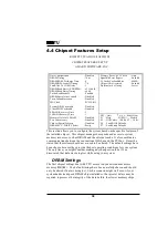
Page 42: ...ts DRAM ECC PARITY Select Parity F7 Load Setup Defaults This section allows you to configure the system based on the specific features of the installed chipset This chipset manages bus speeds and access to system memory resources such as DRAM and the externalcache It also coordinates communicationsbetween the conventionalISA bus and the PCI bus It must be stated that these items should never need ...

Page 43: ...60ns DRAM Timing Type 70ns DRAM Timing Type DRAM must continually be refreshed or it will lose its data Normally DRAM is refreshed entirely asthe result of a single request This option allows you to determine the numberof CPU clocks allocated forthe Row Address Strobe to accumulate itscharge before the DRAM is refreshed If insufficient time is allowed refresh may be incomplete and data lost 3 Thre...

Page 44: ...generated by the CPU in four separate parts The first part provides the location within the DRAM where the read or write is to take place while the remaining three parts provide the actualdata The lower the timing numbers the fasterthe system will address memory x222 x333 Read DRAM EDO FPM timings are 2 2 2 3 3 3 x333 x444 Read DRAM EDO FPM timings are 3 3 3 4 4 4 x444 x444 Read DRAM EDO FPM timin...

Page 45: ...enerated slightly before the address has been fully decoded This can reduce all read latencies More simply the CPU will issue a read request and included with this request is the place address in memory where the desired data is to be found This request is received by the DRAM controller When the peculative Leadoff is enabled the controller will issue the read command slightly before it has finish...

Page 46: ...IOS above enabling the Video BIOS cache will cause access to video BIOS addressed at C0000H to C7FFFH to be cached if the cache controller is also enabled Enabled Video BIOS access cached Disabled Video BIOS access not cached Disabled is the default PCI and IDE Configuration The recovery time is the length of time measured in CPU clocks which the system will delay afterthe completion of an input o...

Page 47: ...to improve performance certain space in memory can be reserved for ISA cards This memory must be mapped into the memory space below 16 MB Enabled Memory hole supported Disabled Memory hole not supported Disabled is the default Peer concurrency means that more than one PCI device can be active at a time Enabled Multiple PCI devices can be active Disabled Only one PCI device can be active at a time ...

Page 48: ...d until software explicit clears the error status flag You can select Enabled or Disabled This item determines the size of the L2 cacheability 64MB 512MB This item allows you to select between two method of chipset NA asserted during CPU write cycles CPU line fills Enabled and Disabled This item allows you to select two timing of pipeline cache Faster and Fastest DRAM ECC PARITY Select Memory Pari...

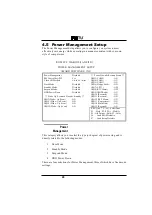
Page 49: ... Disabled IRQ8 RTC Alarm OFF HDD Power Down Disabled IRQ9 IRQ2 Redir ON IRQ10 Reserved ON Wake Up Events In Doze Standby IRQ11 Reserved ON IRQ3 Wake Up Event ON IRQ12 PS 2 Mouse ON IRQ4 Wake Up Event ON IRQ13 Coprocessor ON IRQ8 Wake Up Event ON IRQ14 Hard Disk ON IRQ12 Wake Up Event ON IRQ15 Reserved ON ESC Quit Select Item F1 Help PU PD Modify F5 Old Values Shift F2 Color F6 Load BIOS Defaults F...

Page 50: ...Saving mode and stop the CPU internal clock If the Max Power Saving is not enabled this will be preset to No This determines the mannerin which the monitor is blanked V H SYNC Blank This selection will cause the system to turn off the vertical and horizontalsynchronization ports and write blanks to the video buffer Blank Screen This option only writes blanks to the video buffer DPMS Initial displa...

Page 51: ...stem from such a mode In effect the system remains alert for anythingwhich occurs to a device which is configured as On even when the system is in a power down mode The following is a list of IRQ Interrupt ReQuests which can be exempted much asthe COM ports and LPT ports above can When an I O device wants to gain the attention of the operatingsystem it signals this by causing an IRQ to occur When ...

Page 52: ...t speeds nearing the speed the CPU itself uses when communicatingwith its own special components This section covers some very technical items and it is strongly recommended that only experienced users should make any changes to the default settings ROM PCI ISA BIOS 2A59FI3D POWER MANAGEMENT SETUP AWARD SOFTWARE INC Resources Controlledby Manual PCI IRQ Actived By Level Reset ConfigurationDate Dis...

Page 53: ... PnP F6 Load BIOS Defaults DMA 7 assigned to PCI ISA PnP F7 Load Setup Defaults The Award Plug and Play BIOS has the capacity to automatically configure all of the boot and Plug and Play compatible devices However this capability means absolutely nothing unless you are using a Plug and Play operating system such as Windows 95 Choices are Auto and Manual default This item allows you to determine re...

Page 54: ...in you will note that the primary hasa lower interrupt than the secondary as described in lot x Using INT above Selecting PCI Auto allows the system to automatically determine how your IDE disk system is configured Award s ROM BIOS provides a built in Setup program which allows user modify the system configuration and hardware parameters The modified data will be stored in a battery backed CMOS RA...

Page 55: ...llel port 378H F5 Old Values Shift F2 Color Parallel port Mode ECP EPP1 9 F6 Load BIOS Defaults ECP Mode Use DMA 3 F7 Load Setup Defaults This allows your hard disk controller to use the fast block mode to transferdata to and from your hard disk drive HDD Enabled IDE controller uses block mode Disabled IDE controller uses standard mode Enabled is the default This item allows you designate an IDE c...

Page 56: ...orm the complete task by themselves This simpler and more efficient and faster Your system supports five modes numbered from 0 default to 4 which primarily differ in timing When Auto is selected the BIOS will select the best available mode This is true for the next four setup items 1 IDE Primary MasterPIO 2 IDE Primary Slave PIO 3 IDE Secondary MasterPIO 4 IDE Secondary Slave PIO As stated above y...

Page 57: ...nces between are supervisor password can enter and change the options of the setup menus user password just can enter but do not have the right to change the options of the setup menus When you select this function the following message will appearat the centerof the screen to assist you in creating a password ENTER PASSWORD Type the password up to eight characters in length and press Enter The pa...

Page 58: ...lly detect and configure hard disk parameters The Award BIOS includes this ability in the event you are uncertain of your hard disk parameters 4 11 HDD LOW LEVEL FORMAT If supported by your system this provides a hard disk low level format utility 4 12 SAVE EXIT SETUP Save CMOS value changes to CMOS and exit setup 4 13 EXIT WITHOUT SAVING Abandon all CMOS value changes and exit setup CHAPTER5 SCSI...

Page 59: ...954 Adaptec Inc All Rights Reserved Press Ctrl A for SCSISelect TM Utility SCSI ID 0 SCSI ID 2 SCSI ID 3 SCSI ID 4 MAXTOR QUANTUM Toshiba ARCHIVE P1 17S P40S 94 40 04xx CD_ROM XX3355 VIPER 150 21247 Drive C Drive D 80h 81h BIOS Installed Successfully To start SCSI Select press Ctrl A when the BIOS bannerfirst appears on the screen Note If you only connect a non bootable device this BIOS can not be...

Page 60: ...8xx at Bus Device xx xxh Configure View Host Adapter Setting Use the Up and Down keys and the Enter key to make selections in the SCSI Select utility Press Esc at any time to return to the previous menu Note You can press F5 to toggle the display between color and monochrome modes This feature may not work on some kinds of monitors 5 3 Configure View Host Adapter Settings Menu The Configure View H...

Page 61: ...d with an asterisk throughout the selection submenus 5 3 1 Host Adapter SCSI ID This option allows you to change the host adapterSCSI ID There are 8 available IDs for the P54TS and the 16 available IDs for the P5TSW TSW2 The default setting for both models is SCSI ID 7 which hasthe highest priority on the SCSI bus We recommend that you not to change this setting Note Both in P54TS or P54TSW TSW2 w...

Page 62: ...SCSI bus to verify the correct transmission from your SCSI devices You should disable SCSI Parity Checking if any attached SCSI devices do not support SCSI parity Most currently available SCSI devices do support SCSI parity Use the cursor and Enter keys to make selections Press Esc at any time to return to the previous menu 5 3 3 Host Adapter SCSI Termination This option allows you to configure ho...

Page 63: ...meters of each SCSI device on the SCSI bus Use the cursor keys to move between options Press Enter to display a pop up menu with a selection of values Use the cursor keysx to select a value and press Enter to make yourselection Initiate Sync Negotiation This option determines whether the host adapterinitiates synchronous negotiation with the SCSI device When set to yes the host adapterinitiates sy...

Page 64: ...then the value selected here is the maximum rate that the host adapteraccepts from the device during negotiation This is standard SCSI protocol Note Some older SCSI 1 devices do not support Fast SCSI data transfer rate 10 0 8 0 and 6 7 This may cause yourcomputerto operate erratically or hang if the transferrate is set too high Select a Maximum Sync Transfer Rate of 5 0 for these devices Enable Di...

Page 65: ... device with the lowest SCSI ID When this device responds to the host adapter the Start Unit Command is sent to the next highest SCSI ID with a setting of yes The process continues until all supported devices responds to the host adapter Note If many drivers are set to yes for Send Start Unit Command the boot time varies depending on how long it takes each drive to spin up Include in BIOS Scan The...

Page 66: ...by the SCSI BIOS It is only valid if the SCSI BIOS is enabled The default setting is Boot Only The following choices a re available Boot Only Only the removable media drive designated as the boot device are treated as a hard disk drive All Disks All removable media drives supported by the BIOS are treated as hard disk drives Disabled No removable media drives are treated as hard disk drives In thi...

Page 67: ...ons menu the SCSI Select utility scans the SCSI bus and lists all SCSI devices installed on the SCSI bus You can easily determine from this screen which SCSI ID is assigned to each device on the SCSI bus When you highlight a disk drive by moving to it with the cursor keys and press Enter a small menu window appears You then select Format Disk or Verify Media from this menu Use the cursor keys to m...

Page 68: ...ration You cannot abort a low level format once it is started Verify Disk Media The Verify Disk Media utility scans the selected device s media for defects If the utility finds bad blocks it prompts you to reassign them if you select yes those blocks will no longer be used Note You can press Esc at any time to abort the Verity Disk Media utility APPEDIXA CPU Voltage Selection for Cyrix Processor ...

Page 69: ...P166 GP Cyrix CPU Ordering Number 133Mhz InternalCPU Frequency 028 Operating Voltage Blank 3 3V 5 6x86 full spec 016 3 3V 5 6x86 Cspec 016 028 3 52V 5 6x86 C spec 028 3 52V 028 3 52V with new Marking Note For Dual supply devices knows as M2 M3 project please contact with your Local Cyrix sales offices for advanced information APPEDIXB CPU Voltage Selection for AMD Processor The membersof the AMD5K...

Page 70: ...o help you to set the correct CPU Voltage for AMD Processor The AMD reserves the right to change on this proposed product without notice InternalCPU Frequency Package Type A SPGA Operating Voltage B 3 45V 3 60V C 3 30V 3 465V F 3 135V 3 465V H 2 76V 3 0V 3 135 3 465V core IO I 2 57V 2 84V 3 135V 3 465V core IO AMD logo here K 2 38V 2 63V 3 135 3 465V core IO Case Temperature W 55 C Q 60 C X 65 C A...

Reviews: